AR01.10-P-2400MC | Remove/install engine | 17.4.08 |
ENGINES 275 in MODEL 215, 220 with CODE (487) Active Body Control (ABC)

P01.10-2438-09
Shown on model 220
1 Left air filter housing
2 Vacuum line
3 Expansion reservoir
4 Coolant hose
28 Fuel hose
A9 Refrigerant compressor
A9x1 Refrigerant compressor connector
G2 Generator
17 Hydraulic line
20 Screw
21 Oil cooler line
22 Screw
23 Hydraulic hose
24 Banjo bolt

P01.10-2439-09
5 Coolant hose
6 Coolant hose
7 Coolant hose
27 Vacuum line
29 Screw
8 Heater hose
25 Oil cooler line
26 Transmission oil/fluid line

P01.10-2440-09
9 Oil reservoir
10 Connector
11 Ground cable
12 Feed line
17 Hydraulic line
18 Banjo bolt
19 Nut
13 Feed line
14 Return flow pipe
15 Return flow pipe
16 Plug connection
| Remove/install | ||
Danger! | Risk of death caused by vehicle slipping or toppling off of the lifting platform. | Align vehicle between columns of vehicle lift and position four support plates at vehicle lift support points specified by vehicle manufacturer. | |
Danger! | Risk of injury to skin and eyes caused by scalding from contact with hot coolant spray. Risk of poisoning caused by swallowing coolant. | Do not open cooling system unless coolant temperature is below 90°C. Open cap slowly and release the pressure. Do not pour coolant into beverage containers. Wear protective gloves, protective clothing and safety glasses. | |
Danger! | Risk of injury to skin or eyes caused by hydraulic fluid spraying out under high pressure. Risk of poisoning caused by swallowing hydraulic fluid | Depressurize the hydraulic system completely before starting any work on the system. Wear protective clothing and safety glasses. | |
| Notes on self-locking nuts and bolts | All models | |
1 | Remove transmission | ||
2 | Drain coolant at radiator | ||
3 | Drain coolant for low-temperature circuit | ||
4 | Extract/drain engine oil | ||
| Engine oil and filter change | ||
5 | Remove left air filter housing (1) | ||
6 | Remove poly-V belt | ||
7 | Remove vacuum line (2) to purge control valve | ||
8 | Remove coolant expansion reservoir (3) for coolant | ||
9 | Disconnect coolant hose (4) at alternator (G2) | Inspect condition of coolant hose and hose clamp, replace if necessary. | |
10 | Remove coolant hose (5) from thermostat to radiator and additional radiator | Check condition of coolant hose, O-ring, clamp and hose clamps, replace if required. | |
11 | Disconnect both coolant hoses (6) of low temperature circuit from radiator pipe | Check condition of coolant hoses and hose clamps, replace if required. | |
12 | Remove coolant hose (7) from coolant pump to radiator, expansion reservoir (3) and additional radiator | Check condition of coolant hose, O-ring, clamp and hose clamp, replace if required. | |
13 | Disconnect line to additional radiator | ||
14 | Disconnect heater hose (8) | Check condition of heater hose and clamp, replace if required. | |
15 | Suction off hydraulic fluid from oil reservoir (9) of power steering pump | The oil reservoir of the power steering pump and ABC oil reservoir form one unit and cannot be separated. | |
Hand pump | |||
16 | Suction off hydraulic fluid out of ABC oil reservoir (9) | Hand pump | |
17 | Unplug plug (10) of power steering pump throttle valve | ||
18 | Detach ground cable (11) of power steering pump at body | ||
19 | Disconnect feed line (12) of power steering pump at oil reservoir (9) of power steering pump | Seal the connections. | |
Check condition of hose clamp and feed line (12) and replace if necessary. | |||
Set of plugs | |||
20 | Disconnect feed line (13) of Active Body Control at oil reservoir (9) of Active Body Control | Seal the connections. | |
Check condition of hose clamp and feed line (13) and replace if necessary. | |||
Set of plugs | |||
21 | Disconnect return line (14) of power steering pump at oil reservoir (9) of power steering pump | Seal the connections. | |
Check condition of hose clamp and return line (14) and replace if necessary. | |||
Set of plugs | |||
22 | Disconnect ABC return line (15) from ABC oil reservoir (9) | Seal the connections. | |
Check condition of hose clamp and return line (15) and replace if necessary. | |||
Set of plugs | |||
23 | Disconnect electrical connector (16) from brake system hydraulic unit | ||
24 | Unscrew nuts (19) and remove oil reservoir (9) | ||
25 | Detach hydraulic line (17) of power steering at power steering pump | Seal the connections. | |
Installation: Install new O-ring. | |||
Set of plugs | |||
| |||
26 | Remove banjo bolt (18) of pressure line for Active Body Control at power steering pump | Seal the connections. | |
Installation: Install new O-ring. | |||
Set of plugs | |||
| |||
27 | Remove bolts (20) of oil cooler line (21) at crankcase | Installation: Install new O-ring. | |
| |||
28 | Separate electrical connector (A9x1) of refrigerant compressor (A9) | ||
29 | Remove bolts (22) for refrigerant compressor (A9) | Place refrigerant compressor (A9) with connected lines to the side in engine compartment. | |
| |||
30 | Disconnect hydraulic line (17) of power steering at hydraulic hose (23) and detach from crankcase | Hydraulic line remains in engine compartment. | |
| |||
31 | Remove banjo bolt (24) of Active Body Control hydraulic line at valve unit of pressure supply | Seal the connections. | |
Installation: Install new O-ring. | |||
Set of plugs | |||
| |||
32 | Detach right oil cooler line (25) at oil cooler | Seal the connections. | |
Set of plugs | |||
| |||
33 | Disconnect transmission oil line (26) at radiator | Seal the connections. | |
Set of plugs | |||
| |||
34 | Disconnect engine wiring harness | ||
35 | Detach vacuum line (27) of brake booster at rear intake manifold | ||
Danger! | Risk of explosion caused by fuel igniting, risk of poisoning caused by inhaling and swallowing fuel and risk of injury to eyes and skin caused by contact with fuel | No fire, sparks, open flames or smoking. Wear protective clothing when handling fuel. | |
36 | Disconnect fuel hose (28) at fuel line | Release fuel pressure through service valve. | |
Pressure hose | |||
| |||
37 | Mount rear lifting eye onto engine | Lifting eye | |
38 | Attach engine hoist to engine lifting eyes | Engine hoist | |
39 | Unscrew bolts (29) of front engine mounts at front axle carrier | | |
40 | Lift out engine | Ensure, when lifting out engine that no cables and lines are damaged and that engine does not lean against firewall. | |
Engine hoist | |||
41 | Install in the reverse order | ||
42 | Fill and bleed active body control (ABC) | ||
43 | Fill power steering pump and bleed | ||
44 | Inspecting cooling system for leaks | ||
Danger! | Risk of accident due to vehicle starting off when engine is running Risk of injury caused by contusions and burns during starting procedure or when working near the engine as it is running | Secure vehicle to prevent it from moving by itself. | |
45 | Check for leaks with engine running | ||
46 | Read out fault memory with STAR DIAGNOSIS and erase if necessary | STAR DIAGNOSIS diagnosis system |
Fuel distributor
Number | Designation | Engine | |
BA07.52-P-1002-01E | Union nut connecting fuel feed line to fuel distributor | Nm | 20 |
Oil cooling system
Number | Designation | Engine | |
BA18.30-P-1003-01B | Union nut, oil line to oil cooler | Nm | 30 |
BA18.30-P-1004-01B | Oil line to crankcase | Nm | 8 |
Radiator, coolant hoses
Number | Designation | Engine | ||
BA20.20-P-1001-01A | Union nut, automatic transmission oil line to radiator | Nm | 25 | |
Engine mounts, engine supports
Number | Designation | Engine | Engines | ||
BA22.10-P-1001-01L | Bolt, front engine mount to front axle carrier | Nm | 35 | 35 | |
Active Body Control suspension
Number | Designation | Model | Model | ||
BA32.50-P-1017-01A | Banjo bolt on pressure supply valve unit | Nm | 40 | 40 | |
Power steering pump
Number | Designation | Model | ||
BA46.30-P-1003-01C | High-pressure expansion hose to power steering pump | M141.5 | Nm | - |
M161.5 | Nm | 40 | ||
BA46.30-P-1012-01C | Banjo bolt, high pressure expansion hose (Active Body Control) to power steering pump | Nm | 40 | |
BA46.30-P-1017-01C | Union nut, high pressure hose to power steering pump high-pressure line | Nm | 40 | |
Refrigerant compressor
Number | Designation | Engine | |
BA83.55-P-1001-01A | Bolt, refrigerant compressor to bracket | Nm | 20 |


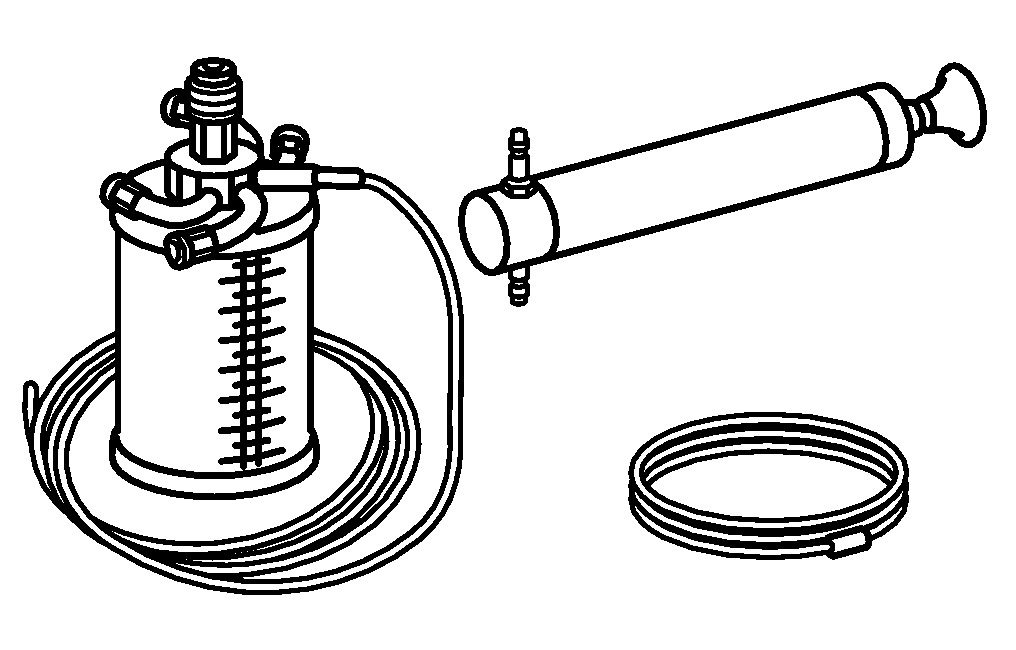

119 589 04 63 00
Hand pump
Pressure hose
Set of stop plugs
Lifting eye
129 589 00 91 00
210 589 00 71 00
285 589 01 61 00
Documentos referenciados
- ah0000n000101a Indicações referentes a parafusos e porcas auto-travantes
- ap1800p0101h Troca do óleo para motor e do filtro de óleo
- ar0910p1150la Remover e instalar a carcaça do filtro de ar
- ar1322p1202l
- ar1518p100002mc
- ar2000p1010ha
- ar2000p1010ha Verificar a estanqueidade do sistema de arrefecimento
- ar2000p1142h Escoar e abastecer o líquido de arrefecimento
- ar2000p1142hm Escoar e encher de agente refrigerante
- ar2710p0500i
- ar2710p0500i Remover e instalar a caixa de mudanças automática com conversor de torque
- ar3250p0021n Abastecer e sangrar o Active-Body-Control (ABC)
- ar4630p0010n
- as0000z000501a Risco de acidente pelo movimento involuntário com o motor em funcionamento. Risco de lesão por esmagamento e queimadura no contato durante o procedimento de partida ou com o motor em funcionamento
- as0000z001001a Perigo de vida pelo escorregamento ou tombamento do veículo do elevador
- as0000z001301a Risco de lesão na pele ou nos olhos por jatos de alta pressão de fluido hidráulico. Risco de intoxicação pela ingestão de fluido hidráulico
- as2000z000101a Risco de lesão na pele e olhos provenientes de queimaduras causadas pelo vapor ou líquido de arrefecimento superaquecido. Risco de envenenamento por ingestão do líquido de arrefecimento
- as4700z000101a Risco de explosão devido a presença de vapores de combustível, risco de envenenamento por inalação e ingestão de combustível bem como risco de lesão pelo contato com a pele e os olhos