Programed repairs Engines 601, 602, 603 Mechanical V
20 Radiator pressure cap
Complaint: Coolant leaking through cooling system cap from 110 °C or higher. |

Cause/Remedy:
Pressure relieve or vacuum valve in cooling system pressure cap faulty, particularly with plastic valve plates.
Filler connection at expansion tank twisted or damaged.
1 Renew radiator cap.
2 Renew expansion tank.
P20-2171-13
20 Coolant pump
Complaint: Residue smears on coolant pump. Engines 601, 602, 603 |
Cause/Remedy:
After vehicle has been standing for a long time, dried coolant residues in the sealing gap of the mechanical seal may cause a temporary leakage when starting.
Coolant drops which in this case flow out of the leak water passage and dry when they drop down, leave clear residue smears because of the high solids content of the coolant (6g/100 cm3)
These residue smears below the coolant pump are not an indication of a leak.
The coolant pump does not need to be renewed for this reason.
20 Fan coupling
Complaint: Noises from the area of the fan coupling, particularly at high engine speeds. Fan constantly running. Coolant temperature too high (engine overheats). Engines 602 and 603.91 |

Cause/Remedy:
Fan coupling from engine 103 installed.
Distinguishing features:
Engines 602 and 603.91
Bimetal spring; color silver grey
Imprinted part no. 603 200 00 22 (arrow).
Engine 103
Bimetal spring; color yellow
Imprinted part no. 103 200 02 22
P20-2170-13
Can be checked with mirror.
Install new fan coupling, part no. 603 200 00 22.
For reasons of space, use short pin wrench
8 mm approx. 25 mm long for slackening and tightening the fastening bolt. Use the 8 mm 3/8" square screwdriver insert part no. 103 589 01 09 00 for this step.
Pay attention to direction of rotation of fan. The cast Part No. on the fan must be at the radiator side.
Tightening torques
Fan to coupling 10 Nm,
Coupling to coolant pump 45 Nm.
20 Fan
Complaint: Clattering noises, particulary when engine cold. When standing in front of vehicle, can be heard most clearly from the area of the radiator lining. Engine 601 in model 201 |
Cause/Remedy:
If the fan is held tight when switched off and pushed slightly forward, the noise is no longer audible.
The armature ring of the magnet coupling attached to the fan by 3 leaf springs is not resting properly against the 3 mounting points at the fan.
The engine vibrations consequently cause it also to vibrate and it strikes against the contact points on the fan.
As there is no remedy at present, it may be necessary to install and listen to the behaviour of several fans.
20 Cooling system
Complaint: Automatic transmission oil in cooling system, expansion tank discoloured red on inside. All models |
The transmission oil cooler in the radiator is attached with aluminium collar nuts on vehicles with automatic transmission.
If these collar nuts have to be replaced in the event of a leak or damage, only steel nuts with steel washer or steel collar nuts may be used.
Tightening torque 25 Nm.
Complaint: Fastening nuts for automatic transmission oil cooler fracture. All engines with automatic transmission |
Model | Bolted connection at water tank | |
|
201.126 Model 201.126 |
top connection bottom connection | Steel collar nut M 201.5 Steel nut M 161.5 Steel washer M 16 |
|
201 (except 201.126) 124 |
both connections | Steel nut M 161.5 Steel washer M 16 |
Designation Part number
Steel nut M161.5 003 990 16 51
Steel washer M16 003 990 77 40
Steel collar nut M201.5 000 990 24 50
Available from: plant 50 (PEW Sindelfingen)
Complaint: High coolant temperatures on vehicles which have covered approx. 6000 km or more. Engines 602, 603 |
Cause/Remedy:
Radiator is blocked with corrosion products.
Radiator remains cold in the middle with the result that the viscous fan coupling does not engage. See also SI 20/30.
Renew radiator.
On no account re-use anti-corrosion/antifreeze. Use only approved anti-corrosion/antifreeze part
no. 000 989 08 25.
20 Coolant pump drainage pipe
Complaint: Retrofitting drainage pipe for coolant pump. Models 124, 126 and 201 with engines 601, 602 and 603 |
Procedure:
1 Drain coolant, pour in (20-010).
2 Remove bottom engine compartment panel, install (01-006).
3 Remove poly V-belt, install (13-342).
4 Remove crankshaft belt pulley and vibration damper, install (03-341).

5 Coat connection fitting (arrow) with adhesive and knock into the bottom vent hole at the coolant pump housing with the drift.
P20-5050-13

6 Push drainage pipe (1) onto the connection fitting using the drift (2).
Shown without dipstick guide tube
P20-5051-13

7 Push drainage (1) behind the dipstick guide tube (2). Turn bottom end of drainage pipe in the direction of the ribbing in the alternator carrier (3) so that any coolant which flows out is channelled into this ribbing.
P20-5054-15
Shop-made tool
Slugging drift.
Material: structural steel e. g. St 37-k.

P20-5062-53
Operation text and flat rates
Retrofitting drainage pipe for coolant pump (during Service Repair).
02-2028-01 Combined operation 15 work units or 1.3 hours
If replacing coolant pump
02-2029-01 Combined operation 5 work units or 0.4 hours
Parts
The drainage pipe is supplied as a parts kit.
Part no. 603 200 17 52
Complaint: Retrofitting vent pipe for cooling system Models 124.128/133/193/333/393 Engines 602.96 and 603.96 (turbo) |
Cause/Remedy:
General
Since mid-October 1989 a vent pipe has been installed on these models for separating vapour bubbles in the cooling system.
Production breakpoint
Model As of vehicle ident end no.
124.128 B 108795
124.133 B 108795
124.193 F 129186
124.333 B 108795
124.393 F 128986
The vent pipe can be retrofitted to models which were produced prior to this production breakpoint if the following problems exist:
e.g. loss of heating capacity
high coolant temperatures (higher than 100 °C), without loss of coolant
coolant loss through overflow reservoir
and after
replacing engine or performing repairs to cylinder head and cylinder head gasket as a result of engine overheating
Note
Before installing the vent pipe, check whether further causes exist for this problems, e.g. check cooling system for leaks.
Vehicles affected
Model Vehicle ident end no. Engine Engine end no.
from to from to
124.128 start of prod. B 108794 602.962 start of prod. 003205*
124.133 start of prod. B 108794 603.960 start of prod. 023891
124.193 start of prod. F 129185 603.960 start of prod. 023891
124.333 start of prod. B 108794 603.963 start of prod. 001863
124.393 start of prod. F 128985 603.963 start of prod. 001863
* On engines with manual transmission from start of production up to engine end no. 000339
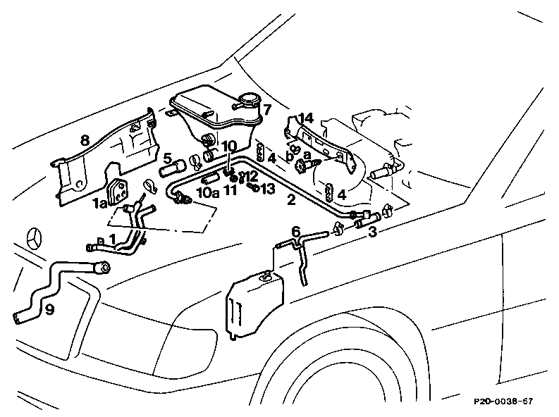
P20-0038-57

1. Remove bottom engine compartment panel (arrows).
2. Drain coolant completely (20-010).
3. Remove bottom coolant hose (item 9).
P01-2289-13

4. Remove air cleaner housing and air guide hose (09-400).
5. Remove coolant expansion reservoir.
6. Remove piping (item 1) at side member; detach hose connections first of all. Slacken partition panel (item 8) and raise sufficiently until pipe assembly (item 1) together with rubber seal (item 1a) can be taken off.
P20.20-0221-13

7. Unbolt cover (item 14) at the component partition by unscrewing both knurled nuts
(item a) and both expansion rivets (item b).
P01-2290-13

8. Press brake pipe for right front wheel out of the two fixtures (item 4) at the firewall.
Note
On model 250 D Turbo unbolt the two fixtures
by turning to the left and replace with new
3-piece fixtures.
Lock brake pipe in the bottom detent of the two fixtures (item 4).
P20-2126-13

9. Disconnect hose (item 6) for feed pipe to heater at heat exchanger.
P20.20-0222-13

10. Install vent pipe (item 2) by pushing pipe through at front left at brake servo unit, beginning at the firewall, and along (parallel to the brake pipe).
11. Insert vent pipe at the left-hand opening into the grommet (arrow).
P01-2287-13

12. On model 250 D Turbo, root vent pipe on the right-hand side between partition and component compartment partition (arrow).
Routing of pipe on model 250 D Turbo
P20.20-0223-13

13. On the 300 D Turbo models, make a hole (about 10 mm ) on the rear of the partition at the top recess (arrow).
Then, route vent pipe through this hole.
P01-2288-13

14. Take rubber seal (item 1a) from the removed piping and fit it onto the modified piping and install piping.
15. Connect vent pipe to piping assembly.
16. Install partition.
P20.20-0224-13

17. On model 250 D Turbo, insert protective sheathing (arrow), part no. 124 997 22 82, at the opening to the partition.
P20.20-0225-13

18. Insert vent pipe into the top detent of the two fixtures at the firewall (arrows).
P20.20-0226-13

19. Attach vent pipe to the right of the firewall with a pipe clip.
On model 250 D Turbo, pierce insulation matting at the existing hole with a suitable drift (arrow).
Model 250 D Turbo
P20-2081-13

On model 300 D Turbo, expose cutout provided (broken line).
On all models, install pipe clip with protective sheathing, M615 bolt and M6 nut (items 10, 11, 12, 13).
Model 300 D Turbo
P20.20-0227-13
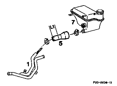
20. Shorten connection hose (item 5) between coolant expansion reservoir (item 7) and piping (item 1) at the bottom end to the piping by
40 mm (L1) and fit onto piping.
21. Take the coolant level sensor out of the removed coolant expansion reservoir and install in new expansion reservoir.
L 1 = 40 mm
P20-0039-13

22. Install new coolant expansion reservoir and connect hoses.
23. Install air cleaner and air guide hose
(09-400).
P20.20-0228-13
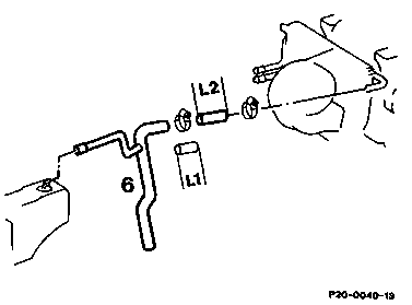
24. Shorten the feed hose (item 6) at the disconnected end by 30 mm (L2). Fit the section cut off onto the pipe connection of the heater box.
Then, once again shorten the feed hose by
25 mm (L1).
L1 = 25 mm
L2 = 30 mm
P20-0040-13

25. Insert distributor (item 3) into the feed hose and connect vent pipe.
P20.20-0229-13
26. Install cover (item 14) at firewall.
27. Install new bottom coolant hose (item 9).
28. Install engine compartment panel.
29. Pour in coolant (20-010).
30. Check cooling system for leaks.
Operation text and time allowance
Model 124.128/133/193/333/393
Retrofitting vent pipe for cooling system
02-2024/01 basic work 36 work units or 3.0 h.
02-2025/01 corrected work 33 work units or 2.8 h.
The book/column number of the appropriate model should be added as a prefix to the operation number.
Parts
Qty. Designation Part no. Required for models
250 D Turbo 300 D Turbo
1 Coolant expansion reservoir 124 500 11 49 X X
1 Coolant hose 124 501 48 82 X -
1 Coolant hose 124 501 49 82 - X
1 Piping assembly 124 830 24 15 X X
1 Vent pipe 124 830 28 15 X X
1 Distributor pipe 124 830 26 15 X X
2 Hose clip 916026 020001 X X
1 Fixture 108 995 05 20 X X
2 Fixture 201 995 02 65 X X
1 Protective sleeving 124 997 22 82 X X
1 Protective sleeving 126 328 01 81 X X
1 M615 hexagon bolt 000933 006207 X X
1 M6 nut 003 990 08 51 X X
Powiązane dokumenty
- ar0330p1600hw Demontaż i montaż koła pasowego / tłumika drgań
- ar1322p1202hw Demontaż i montaż paska klinowego
- ra01006010006x
- ra09006010400x
- ra20006010010x
- ra2000601ta04x