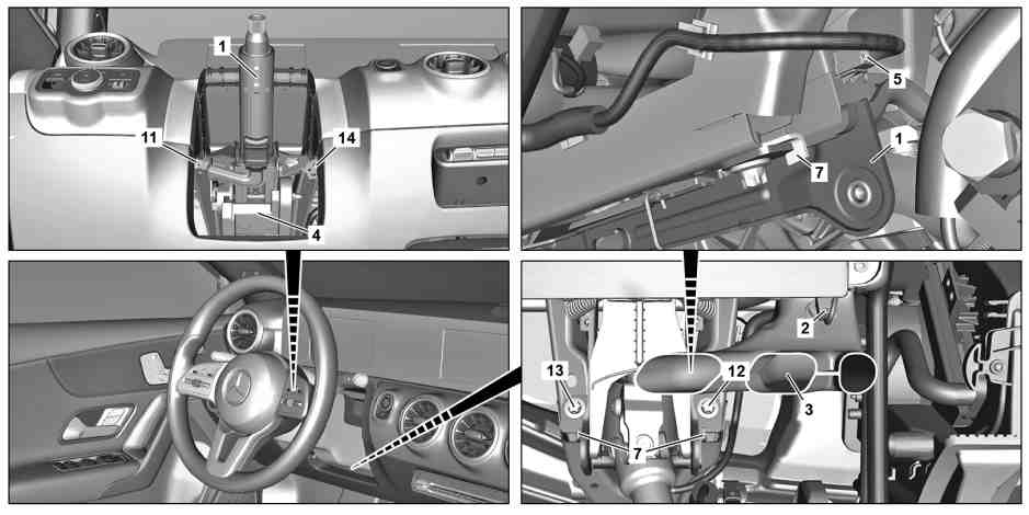
P46.10-3662-09
1 | Steering column tube | 7 | Catch hook | |
2 | Electrical connector | 11 | Screw | |
3 | Air duct | 12 | Screw | |
4 | Knee bolster | 13 | Screw | |
5 | Electrical connector | 14 | Screw |
Topical note | Notes on self-locking nuts and bolts | ||
Topical note | Information on preventing damage to electronic components due to electrostatic discharge | ||
Notes on safety-relevant components | |||
| Remove/install | ||
1 | Move steering column tube (1) forward and upward. | ||
2 | Remove steering column tube module control unit (N80). | ||
3 | Remove trim at bottom for instrument panel on driver's side. | ||
4 | Release and disconnect electrical connector (2) and remove air duct (3). | ||
5 | Unclip knee bolster (4). | Model 118, 177, 247 | |
Installation: When replacing the steering column tube (1), the knee bolster (4) must be replaced. | |||
The plastic carrier plate of the knee bolster (4) remains on the steering column tube (1). | |||
6 | Remove driver kneebag. | Model 118, 177, 247 | |
7 | Disconnect steering coupling. | ||
Clamp screw, steering coupling to rack-and-pinion steering | |||
Retainer device | |||
8 | Release and disconnect electrical connector (5). | ||
9 | Remove screws (11, 12, 13, 14) in reverse numerical order. | Bolt, jacket tube to cross member | |
10 | Pull steering column tube (1) opposite to the direction of travel, move out of catch hooks (7) on left and right and remove steering column tube (1). | Installation: Make sure that the steering column tube (1) inserts correctly into the catch hooks (7) on left and right. | |
11 | Transfer electric steering lock control unit (N26/5). | If the steering column tube (1) is replaced. | |
Model 118, 177, 247 | |||
12 | Install in the reverse order. | ||
Concluding tasks | |||
13 | Update Vehicle Documentation (VeDoc). | If the steering column tube (1) is replaced. | |
|

129 589 01 21 00
Retainer device
Powiązane dokumenty
- ad0000p200006mfa
- ah0000n000101a Wskazówki dotyczące samozabezpieczających śrub i nakrętek
- ah0000z001901a Wskazówki dotyczące elementów wpływających na bezpieczeństwo
- ah5400p000101a Wskazówki dotyczące zapobiegania uszkodzeniom elementów elektronicznych na skutek rozładowania potencjału elektrostatycznego
- ar4610p0920mfa
- ar4610p800001mfa
- ar5425p2802mfa
- ar6810p1501mfa
- ar9160p0200mfa