S20.00-A016-79
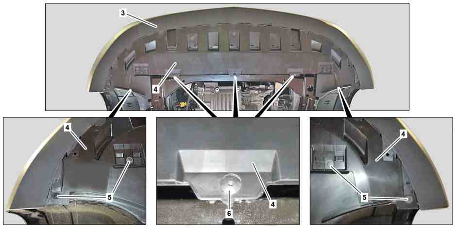
3 | Front bumper | 5 | Expansion rivets | |
4 | Cover | 6 | Screw |

S31.35-A000-79
1 | Frame-type integral support | 8 | Screw | |
2 | Bracket | 9 | Universal joint | |
7 | Tensioning strap | 10 | Electrical connectors |

S31.35-A001-79
Shown on model 447 with code FY1 (Anti-Theft Protection Package) |
11 | Electrical connector | 15 | Equipotential bonding line | |
12 | Alarm siren | 16 | High-voltage lines | |
13 | Electrical wiring harness | 17 | Screw | |
14 | Electrical wiring harness | 18 | Bolts |
Danger | Risk of death caused by vehicle slipping or toppling off of the lifting platform. | Align vehicle between vehicle lift columns and position the four support plates at the vehicle lift support points specified by the vehicle manufacturer. | |
Danger | Risk of death when working on component parts and systems with U >= 30 V alternating voltage (AC) or U >= 60 V direct voltage (DC) | Do not touch damaged or defective live component parts and lines or non-insulated electrical connections and lines. | |
Topical note | General information on vehicles with high-voltage on-board electrical system and/or lithium-ion battery and/or gaseous-fuel drive system as well as personal protective equipment | ||
| Remove/install | ||
1 | Perform power disconnect of high-voltage on-board electrical system. | ||
2 | Set steering gear to center position. | ||
Retainer device | |||
3 | Remove left and right transverse control arms of front axle. | ||
4 | Secure vehicle on vehicle lift. | ||
5 | Remove expansion rivets (5). | Clip remover | |
6 | Remove screw/bolts (6). | ||
7 | Push trim (4) forward and detach from integral carrier (1). | ||
8 | Remove trim (4) from front bumper (3) towards the rear. | Installation: Make sure that the trim (4) is seated correctly on the retaining tabs of the front bumper (3). | |
9 | Secure radiator package on lower brackets (2) with tensioning straps (7) at left and right longitudinal member front sections. | ||
10 | Remove screw (8) and detach universal joint (9) from steering gear. | ||
Topical note | Notes on threaded connections fastened using a tightening angle-based tightening process | ||
Topical note | Notes on self-locking nuts and bolts | ||
Installation: Replace bolt (8). | |||
Bolt, universal joint to steering gear | |||
11 | Disconnect electrical connectors (10). | ||
12 | Disconnect electrical connector (11) from alarm siren (12). | Model 447 with engine 780.701 | |
13 | Unclip electrical wiring harness (13) (arrow A). | Model 447 with engine 780.701 | |
Clip remover | |||
14 | Unclip electrical wiring harness (14) (arrow B). | Clip remover | |
15 | Unclip equipotential bonding line (15) (arrow C). | Clip remover | |
16 | Unclip high-voltage lines (16) (arrows D). | Clip remover | |
17 | Remove screw (17). | Screw, engine stabilizer mount at bottom to axle drive module | |
18 | Support integral carrier (1) and secure on mounting plate. | ||
| 000 588 11 62 00 Major assembly mount | ||
| 000 588 10 62 00 Support plate | ||
19 | Remove screws (18). | Bolt, integral carrier to longitudinal frame member | |
20 | Remove integral carrier (1). | Installation: Make sure that the elastomer bearings are correctly seated on the brackets (2) of the radiator package. | |
Helper required. | |||
21 | Detach steering gear from integral carrier (1). | When replacing the frame-type integral support (1). | |
22 | Install in the reverse order. | ||
23 | Perform chassis alignment. | ||
| Check | ||
24 | Perform function test on electrical power steering. | ||
25 | Perform function test of alarm siren (12) | Model 447 with engine 780.701 |


452 589 01 63 00
Clip remover
129 589 01 21 00
Retainer device
Powiązane dokumenty
- ah0000n000101a Wskazówki dotyczące samozabezpieczających śrub i nakrętek
- ah0000p002001a Wskazówki dotyczące połączeń śrubowych tworzonych według kąta dokręcenia
- ah0000z030001a Ogólne wskazówki dotyczące pojazdów z instalacją wysokiego napięcia i/lub akumulatorem litowo-jonowym i/lub gazowym systemem napędu oraz osobistego wyposażenia ochronnego
- ar0060s0100e
- ar3320s1452ef
- ar4020s0200e
- ar4020s0200e
- ar4620s050001e
- ar4620s0500f
- ar4770s1000f
- as0000z001001a Zagrożenie życia na skutek ześlizgnięcia lub spadnięcia pojazdu z podnośnika.
- as0000z003501a Zagrożenie życia podczas prac przy elementach i systemach U >=30 V napięcie zmienne (AC) bądź U >=60 V napięcie zmienne
- ws0100p0092b
- ws2600p3309b