D08.50-A024-79
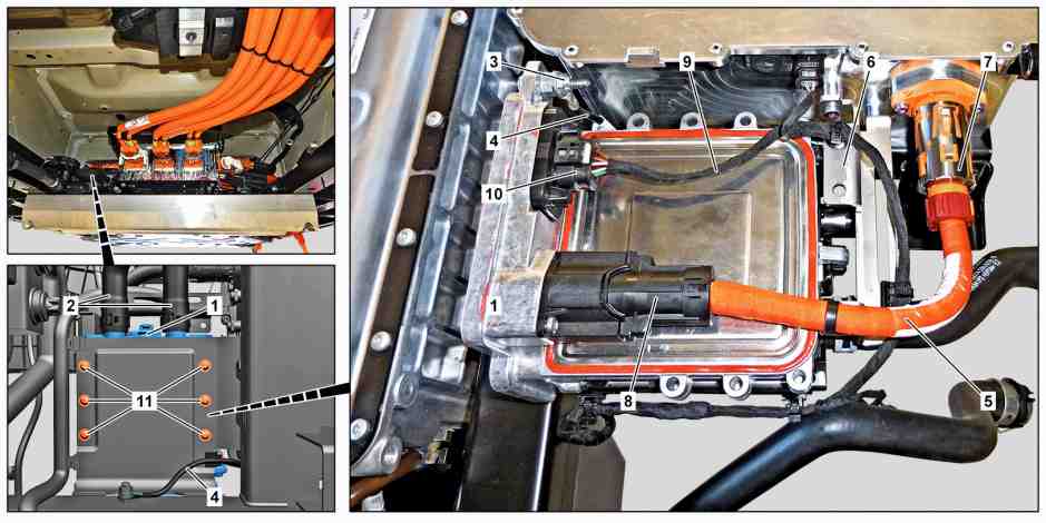
1 | Heater unit | 5 | High-voltage line | 9 | Electrical line | ||
2 | Coolant hoses | 6 | Bracket | 10 | Electrical connector | ||
3 | Nut | 7 | High-voltage plug | 11 | Bolts | ||
4 | Ground cable | 8 | High-voltage plug |
Danger | Risk of death when working on component parts and systems with U >= 30 V alternating voltage (AC) or U >= 60 V direct voltage (DC) | Do not touch damaged or defective live component parts and lines or non-insulated electrical connections and lines. | |
Warning | Risk of injury to skin and eyes suffering scalding from contact with hot coolantspray. Risk of poisoning from swallowing coolant. | Do not open cooling system unless coolant temperature is below 90 °C. Open cap slowly and release the pressure. Do not pour coolant into beverage containers. | |
Topical note | General information on vehicles with high-voltage on-board electrical system and/or lithium-ion battery and/or gaseous-fuel drive system as well as personal protective equipment | ||
Topical note | Information on preventing damage to electronic components due to electrostatic discharge | ||
Topical note | Notes on battery | ||
| Remove/install | ||
1 | Remove switchover valve at underbody and place to one side. | ||
In this connection, coolant of auxiliary circuit is already drained. | |||
2 | Remove voltage of high-voltage on-board electrical system. | ||
3 | Remove coolant hoses (2) from heater (1). | Collect escaping coolant. | |
Record plug | |||
Hose clamp pliers | |||
4 | Remove ground line (4) at heater (1). | Check ground lines for high-voltage on-board electrical system potential equalization | |
Topical note | Notes on self-locking nuts and bolts | ||
For this purpose, remove nut (3). | |||
Installation: Check ground line (4). | |||
Nut, potential equalization ground line to auxiliary circuit heater holder | |||
Nut, potential equalization ground line to auxiliary circuit heater holder | |||
5 | Remove high voltage line (5) from bracket (6). | Installation: Check retaining clips for damage. | |
Clip remover | |||
Depending on the findings, | |||
| |||
Replace damaged retaining clip. | |||
6 | Release and disconnect high-voltage plug (7) at high-voltage power distributor. | WIS Service Media | |
7 | Remove high voltage line (5). | For this purpose, release and disconnect high-voltage plug (8) at heater (1). | |
8 | Cover high-voltage connections at heater (1) and at high-voltage power distributor at underbody with suitable protective covers. | Set of protective covers | |
9 | Remove electric line (9) from bracket (6). | Installation: Check retaining clips for damage. | |
Clip remover | |||
Depending on the findings, | |||
| |||
Replace damaged retaining clip. | |||
10 | Disconnect electrical connector (10). | ||
11 | Remove bracket (6). | Bolt, holder to high-voltage power distributor/holder | |
12 | Remove screws (11). | Screw, auxiliary circuit heater to holder | |
13 | Remove heater (1). | | |
14 | Install in the reverse order. | ||
| Check | ||
15 | Perform commissioning of heater (1) with vehicle diagnosis system. | If heater (1) will be replaced. | |
|


454 589 00 37 00
Hose clamp pliers
001 589 01 91 00
Set of protective covers
452 589 01 63 00
Clip remover
129 589 00 91 00
Record plug
Powiązane dokumenty
- ad0000d200006ts
- ah0000n000101a Wskazówki dotyczące samozabezpieczających śrub i nakrętek
- ah0000z030001a Ogólne wskazówki dotyczące pojazdów z instalacją wysokiego napięcia i/lub akumulatorem litowo-jonowym i/lub gazowym systemem napędu oraz osobistego wyposażenia ochronnego
- ah5400p000101a Wskazówki dotyczące zapobiegania uszkodzeniom elementów elektronicznych na skutek rozładowania potencjału elektrostatycznego
- ah5410p000101a Wskazówki dotyczące akumulatora
- ah5410p000101a
- ar0850d0031te
- ar0850d0031te
- ar4770d1000te
- ar4770d102001te
- as0000z003501a Zagrożenie życia podczas prac przy elementach i systemach U >=30 V napięcie zmienne (AC) bądź U >=60 V napięcie zmienne
- as2000z000101a Niebezpieczeństwo zranienia skóry i oczu przez poparzenie wytryskującym, gorącympłynem chłodzącym. Niebezpieczeństwo zatrucia na skutek połknięcia płynu chłodzącego