
2 | Compensating element |
3 | Cam |
4 | Roller cam follower |
5 | Tool |
P05.00-2063-11
| Check | ||
1 | Check engine oil level. Correct if necessary | ||
| Low SPAsh multigrade service engine oils (specification 228.51) | ||
| Low SPAsh multigrade service engine oils (specification 229.31) | ||
| |||
| Remove/install | ||
Danger ! | Risk of accident from vehicle starting off by itself when engine running. Risk of injury (bruises and burns) resulting from working on the engine while it is being started or when it is running. | Secure vehicle to prevent it from starting off by itself. Wear closed and snug-fitting work clothes. Do not touch hot or rotating parts. | |
2 | Start engine and warm up to normal operating temperature (approx. 80°C) | ||
3 | Remove cylinder head cover | ||
| Check | ||
4 | Rotate engine at crankshaft in direction of engine rotation until the cam (3) on the compensating element (2) to be checked is on its base circle | | |
Counterholder | |||
Counterholder | |||
5 | Press down compensating element (2) over roller cam follower (4) by hand using the appropriate tool (5) | | |
If a number of compensating elements (2) drop, check oil ducts and oil feed bores for the compensating elements (2) for fouling; blow out the oil ducts with compressed air in the flow direction of the oil if necessary. | |||
If a compensating element (2) drops much more than other compensating elements (2), replace compensating element (2) in question: | |||
| |||
Remove/install hydraulic valve clearance compensating elements | |||
6 | Install in the reverse order |
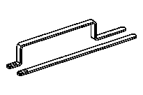
651 589 00 40 00
Counterholder
651 589 08 40 00
Counterholder
Powiązane dokumenty
- ar0120s5014e
- ar0500s2011e
- as0000z000501a Niebezpieczeństwo wypadku na skutek samoczynnego ruszenia przy pracującym silniku. Niebezpieczeństwo obrażeń na skutek zmiażdżenia lub poparzenia przy wykonywaniu czynności podczas rozruchu lub przy pracującym silniku.
- bb0040p022851a Oleje wielosezonowe serwisowe Low SPAsh (specyfikacja 228.51)
- bb0040p022931a Oleje wielosezonowe serwisowe Low SPAsh (specyfikacja 229.31)