
2 | Crankcase |
5 | Bearing shell |
6 | Fitted bearing shell with thrust plates |
7 | Balance shaft housing |
8 | Screw |
9 | Oil suction pipe |
D03.20-1189-06
| Remove | ||
1 | Remove engine and install on assembly stand | ||
| 000 588 00 31 00 Assembly stand | ||
| 000 588 00 31 02 Adapter | ||
2 | Remove flywheel or driven plate | ||
3 | Remove timing case cover | ||
4 | Remove oil pan |
| |
Model 447 with engine 651 | |||
5 | Remove oil suction pipe (9) | ||
Bolt, oil suction pipe to bearing housing | |||
6 | Move engine to basic position and arrest | ||
The hold-down tool remains on the camshafts and the assembly tool remains on the balance shafts in the balance shaft housing (7). | |||
Bolt connecting camshaft bearing cap to cylinder head | |||
Counterholder | |||
Counterholder | |||
Holddown device | |||
Assembly tool | |||
7 | Remove end cover with radial shaft sealing ring | ||
8 | Remove screw/bolts (8) in the reverse order of the tightening procedure | ||
Bolt, crankshaft bearing cap | |||
9 | Remove balance shaft housing (7) | The balance shaft housing (7) serves as a crankshaft bearing cap. | |
10 | Remove bearing shells (5) and fitted bearing shells with thrust plates (6) on balance shaft housing (7) | Mark bearing shells (5) and fitted bearing shells with thrust plates (6) in relation to corresponding crankshaft bearing. | |
| Clean | ||
11 | Clean sealing surfaces and storage areas on crankcase (2) or balance shaft housing (7) | | |
Cold degreasing agent/cold cleaning solvent HAKU 1025-920 | |||
| Check | ||
12 | Check screw/bolts (8) on balance shaft housing (7) | ||
Crankshaft bearing cap bolts M12 | |||
| Install | ||
13 | Insert bearing shells (5) and fitted bearing shells with thrust plates (6) into balance shaft housing (7) | Lubricate bearing shells (5) and fitted bearing shell with thrust plate (6). Observe marking on bearing shells (5). | |
14 | Install crankshaft bearing cap (7) with locked balance shafts on crankcase (2) | Ensure that the pilot bushings is seated correctly. | |
15 | Screw in screw/bolts (8) accorded to the tightening procedure | ||
Lubricate screw/bolts (8) on thread and bolt head contact surface. | |||
Bolt, crankshaft bearing cap | |||
16 | Install end cover with radial shaft sealing ring | ||
17 | Remove catch for engine | ||
Bolt connecting camshaft bearing cap to cylinder head | |||
Counterholder | |||
Counterholder | |||
Holddown device | |||
Assembly tool | |||
18 | Set piston on cylinder 1 to TDC (TDC) | ||
Counterholder | |||
Counterholder | |||
19 | Install oil suction pipe (9) | ||
Bolt, oil suction pipe to bearing housing | |||
20 | Install oil pan |
| |
Model 447 with engine 651 | |||
21 | Install timing case cover | ||
22 | Install flywheel or driven plate | ||
23 | Install engine |

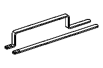

651 589 02 63 00
Assembly tool
651 589 00 40 00
Counterholder
651 589 08 40 00
Counterholder
651 589 09 40 00
Holddown device