
1 | Cylinder head cover |
2 | Engine charge air duct |
11 | Screw |
12 | Fuel line |
14 | Fuel hose |
15 | Fuel hose |
16 | Fuel filter |
17 | Screw |
18 | Electrical wiring harness |
19 | High pressure pump |
D01.20-A001-06

7 | Screw |
22 | Bracket |
25 | Bracket |
26 | Hose |
27 | Hose |
28 | Bracket |
29 | Bracket |
34 | Glow output stage |
D01.20-A002-12
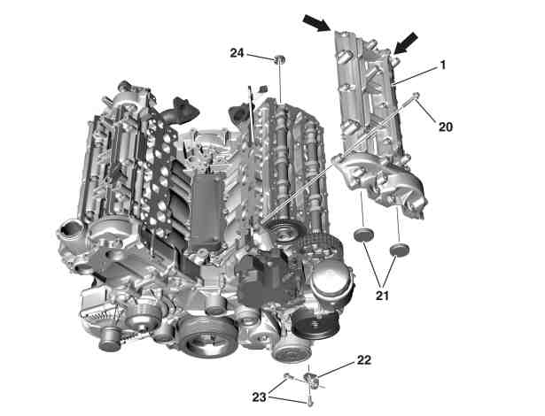
1 | Cylinder head cover |
20 | Screw |
21 | Cover |
22 | Bracket |
23 | Bolts |
24 | Cover |
D01.20-1025-06
Warning | Risk of injury. Skin or eye injuries may result when handling hot or glowing objects. | Wear protective gloves, protective clothing and safety glasses, if necessary. | |
Caution | Risk of injury to skin and eyes due to handling of engine oil. Risk of poisoning caused by swallowing engine oil | Wear protective gloves, protective clothing and safety glasses. | |
Danger | Risk of explosion caused by fuel igniting, risk of poisoning caused by inhaling and swallowing fuel as well as risk of injury to eyes and skin caused by contactwith fuel. | No fires, sparks, open flames or smoking. Pour fuels into suitable and appropriately marked containers only. | |
Topical note | Notes on avoiding damage through contamination and foreign objects | ||
| Remove/install | ||
1 | Remove screw (7) and press bracket (25) with hose (26) forward. | ||
2 | Remove engine charge air duct (2) and hang to one side. | ||
3 | Remove rail of the left cylinder head. | ||
4 | Remove injectors of the left cylinder head. | ||
5 | Remove bracket (29) with glow output stage (34) and place to one side. | Unclip hose (27) from bracket (28). Do not disconnect electrical connectors of glow output stage (34). | |
Bolt, bracket to charge-air distributor | |||
6 | Remove high-pressure line to rail. | ||
7 | Remove fuel hose (14) from high-pressure pump (19). | Seal openings with suitable stop plug. | |
Installation: Check clamp for damage. | |||
Pliers for click clamps | |||
Record plug | |||
In the case of damage, | |||
| |||
Replace clamp. | |||
8 | Remove fuel hose (15) from fuel filter (16). | Seal fuel hose (15) and connection on fuel filter (16) with suitable stop plugs. | |
Installation: Check clamp for damage. | |||
Pliers for click clamps | |||
Record plug | |||
In the case of damage, | |||
| |||
Replace clamp. | |||
9 | Remove electrical wiring harness (18) from cylinder head cover (1). | Installation: Check retaining clamps of the electrical wiring harness (18) for damage. | |
In the case of damage, | |||
| |||
Replace retaining clips. | |||
10 | Remove screws (11, 17) and position fuel line (12) outside the working area. | ||
11 | Remove screws (23) and remove bracket (22). | Bolt, holder to oil filter housing and cylinder head cover | |
12 | Loosen and remove screws (20) in stages and in reverse order of the tightening procedure for a cooled engine. | Bolt tightening procedure for cylinder head cover | |
Removal: | |||
Installation: | |||
Screw/bolt, cylinder head cover to cylinder head | |||
13 | Remove the cylinder head cover (1). | ||
Notes on sealant path for cylinder head cover | |||
Removal: | |||
Removal: Carefully pry off the cylinder head cover (1) to the corners (arrows) from the cylinder head with a suitable tool. | |||
A new cylinder head cover (1) can be installed only in combination with the cylinder head. | |||
Installation: Install new caps (21, 24). | |||
Sealant, Loctite 5970, 50 ml | |||
Loctite 7200 | |||
Application gun | |||
14 | Install in the reverse order. | ||
| Check | ||
Warning | Risk of accident from vehicle starting off by itself when engine running. Risk of injury (bruises and burns) resulting from working on the engine while it is being started or when it is running. | Secure vehicle to prevent it from starting off by itself. Wear closed and snug-fitting work clothes. Do not touch hot or rotating parts. | |
15 | Perform engine test run and check engine in the area of the cylinder head cover (1) for leak tightness. | Visual inspection only. |


112 589 00 25 00
Application gun
129 589 00 91 00
Record plug
171 589 00 37 00
Pliers for click clamps
Powiązane dokumenty
- ah0000p500001a Wskazówki dotyczące zapobiegania uszkodzeniom na skutek zabrudzeń i ciał obcych
- ah0130n100008se Wskazówki dotyczące przebiegu środka uszczelniającego na pokrywie głowicy cylindrów
- ar0120d501403sf Schemat dokręcania śrub pokrywy głowicy cylindrów
- ar0703d1011tsv
- ar0716d1004tsv
- ar0716d1020tsv
- ar0941d8950tsv
- as0000z000201a Niebezpieczeństwo zranienia skóry i oczy na skutek kontaktu z gorącymi lub żarzącymi się przedmiotami
- as0000z000501a Niebezpieczeństwo wypadku na skutek samoczynnego ruszenia przy pracującym silniku. Niebezpieczeństwo obrażeń na skutek zmiażdżenia lub poparzenia przy wykonywaniu czynności podczas rozruchu lub przy pracującym silniku.
- as1800z000101a Niebezpieczeństwo obrażeń skóry i oczu podczas kontaktu z olejem silnikowym. Niebezpieczeństwo zatrucia wskutek połknięcia oleju silnikowego
- as4700z000101a Niebezpieczeństwo wybuchu wskutek zapalenia, niebezpieczeństwo zatrucia wskutek wdychania i połknięcia paliwa oraz niebezpieczeństwo obrażeń wskutek kontaktu skóry i oczu z paliwem.