AR26.10-D-0020AD | Remove/install transmission | 15.2.12 |
TRANSMISSION 712.613 in MODEL 668, 670 with ENGINE 900.917 /918 /919
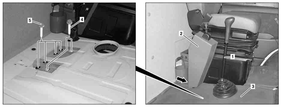
D26.10-1134-08
1 Gearshift lever
2 Trim
5 Bolt
3 Floor Covering
4 Bolt
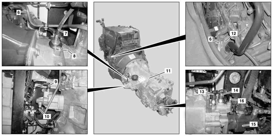
D26.10-1135-09
6 Compressed-air line
7 Remove clutch line
8 Securing clamp
13 Electrical connector
14 Electrical connector
15 Hydraulic pump to power take-off
16 Compressed air connection
9 Electrical connector
10 Electrical connector
11 Transmission
12 Compressor

11 Transmission
17 Mounting adapter
18 Transmission jack
19 Bolt
20 Lashing strap
D26.10-1136-03
| Remove/install | ||
Danger! | Risk of poisoning caused by swallowing brake fluid. Risk of injury caused by brake fluid coming into contact with skin and eyes. | Pour brake fluid only into suitable and appropriately marked containers. Wear protective clothing and eye protection when handling brake fluid. | |
1 | Extract brake fluid using suitable vacuum unit from the expansion reservoir of the hydraulic clutch system | ||
| Brake fluid notes | ||
Danger! | Risk of explosion caused by escaping oxyhydrogen gas. Risk of injury caused by caustic burns to eyes, skin and mucous membranes from battery electrolyte (contains diluted sulfuric acid) or metal spatter due to short circuit. Risk of burn injuries caused by short circuit. Risk of poisoning caused by swallowing battery electrolyte (contains diluted sulfuric acid) or absorption of lead over the skin or orifices | No fire, sparks, open flames or smoking. Wear acid-resistant gloves and clothing and safety glasses with side guards. Do not place any conductive objects on the battery and avoid any short circuit from battery positive to ground. Only fill liquid battery electrolyte (diluted sulfuric acid) into suitable and appropriately marked containers. | |
2 | Disconnect ground lead from battery | ||
| Notes on battery | ||
3 | Remove soundproofing on lower frame | Only for model 668, 670.3 with | |
Installation: Install soundproofing on lower frame only after performing function- and leak test first. | |||
4 | Remove service cover | Installation: Only install maintenance cover after first performing a function- and leak test. | |
5 | Remove passenger seat | | |
| |||
6 | Remove compressed air line (6) on compressor (12) | ||
7 | Remove exhaust pipe | ||
8 | Remove shift lever (1). | ||
9 | Unclip trim (2) on parking brake | ||
10 | Separate floor covering (3) in area of compressed air lines for the parking brake (arrow) and push back far enough until the openings for the screws (4, 5) are accessible | ||
11 | Remove compressed-air line (6) and check for carbon deposits | In the event of carbonization, also check the compressed air lines between the compressor (12), compressed air drier and the four-circuit protection valve, if necessary replace the carbonized parts. | |
Danger! | Risk of poisoning caused by swallowing brake fluid. Risk of injury caused by brake fluid coming into contact with skin and eyes. | Pour brake fluid only into suitable and appropriately marked containers. Wear protective clothing and eye protection when handling brake fluid. | |
12 | Withdraw safety clamp (8) and detach clutch line (7) from connection for central clutch release bearing | Collect escaping brake fluid. Seal connections on the central clutch release bearing and clutch line (7) using suitable stop plugs. | |
| |||
| Brake fluid notes | ||
13 | Drain transmission oil | Only for vehicles with power take-off on the transmission (11). | |
| Manual transmission - oil change | ||
14 | Remove the hydraulic pump for power take-off (15) from the transmission (11) and place to one side with connected hydraulic lines | Only for vehicles with power take-off on the transmission (11). | |
15 | Remove compressed air connection (16) from transmission (11) | Only for vehicles with power take-off on the transmission (11). | |
16 | Remove propeller shaft on the transmission (11) and strap down to one side | ||
| |||
17 | Remove the propeller shaft on the front axle gear and strap down to one side | Only for model 670.4 with engine 900.917/918 and transmission 712.613 | |
| |||
18 | Detach electrical connectors (9, 10, 13, 14) | Installation: Replace lead seal of connector (13). | |
19 | Position transmission jack (18) with mounting adapter (17) under the transmission (11) and secure transmission (11) with lashing strap (20) against falling down | | |
| |||
| |||
20 | Support engine on timing case with the inspection pit lift | This prevents the engine tilting backwards when the transmission (11) is removed. | |
Pit lift | |||
21 | Remove bolts (4, 5) | Insert the socket from below onto the bolts (4, 5) and unscrew the bolts (4, 5) with aid of 2nd. technician from above through the assembly bores. | |
| |||
22 | Remove bolts (19) | | |
23 | Lower engine with inspection pit lift and transmission (11) with transmission jack (18) at the same time far enough until the transmission (11) can be pulled out of the engine | When lowering the engine with the transmission (11) make sure that no other components are damaged. | |
| |||
| |||
| |||
Pit lift | |||
24 | Completely lower the transmission jack (18) with the transmission (11) | | |
| |||
| |||
25 | Install in the reverse order | ||
26 | Bleed clutch operating system | ||
27 | Check transmission oil level, correct if necessary | Only for vehicles without power take-off on the transmission (11). | |
| Manual transmission - oil change | ||
28 | Check transmission (11) for proper operation and leaktightness |
Complete manual transmission
Number | Designation | Transmission | |
BA26.10-N-1013-01D | Transmission to flywheel housing | Nm | 45 |
BA26.10-N-1014-01D | Supporting arm to transmission | Nm | 190 |
Propeller shaft
Number | Designation | Model | ||
BA41.10-N-1001-01D | Propeller shaft to transmission | M101 | Nm | 62 |
M121.5 | Nm | 100 | ||
BA41.10-N-1008-01D | Bolt for propeller shaft to front axle drive flange | Nm | 60 | |
Front seats
Number | Designation | Model 667, 668, 670 | |
BA91.10-N-1001-01D | Front bolt of passenger seat to body | Nm | 20 |
BA91.10-N-1002-01D | Rear bolt of front passenger seat to body | Nm | 28 |

Set of stop plugs
129 589 00 91 00
Commercially available tools
Number | Designation | |
WH58.30-Z-1004-07A | Universal mounting adapter | |
WH58.30-Z-1020-07A | Lashing strap, 25 mm width (1000daN), |
Workshop equipment
WE58.40-Z-1002-05A | Pit lift |
WE58.40-Z-1030-11A | Transmission jack |