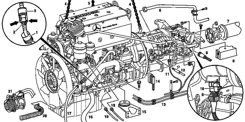
W01.10-0013-09
1 | Cap (only in the case of engine 904.9) | 8 | gear support | 15 | Engine mounting block | ||
2 | Compressed air tube coupler (only in the case of engine 904.9) | 9 | Electric connection | 16 | Steering gear suction manifold | ||
3 | Compressed air manifold connector (only in the case of engine 904.9) | 10 | Seal | 17 | Steering gear pressure manifold | ||
4 | Suspension chain | 11 | Electric connection | 18 | Fuel manifold, flow | ||
5 | suspension chain | 12 | Clutch manifold | 19 | Fuel manifold, return | ||
6 | Compressed air piping | 13 | Electric wiring harness | 20 | Oil filler tube | ||
7 | Transmission shaft | 14 | Electric connection | 21 | Coolant compressor (only for code (H03), front part air conditioning system) |

W01.10-1035-09
22 | Exhaust pipe | 26 | Compressed air piping | 29 | Ground wire | ||
23 | Clamp | 27 | Electric wiring harness | G2 | Alternator | ||
24 | Air suction hose | 28 | Terminal 30 electric wire | M1 | Starting motor | ||
25 | Electric wiring harness |
| Remove/install | ||
Danger | Risk of fire/risk of explosion due to short circuit and escaping oxyhydrogen gas. Risk of (burn) injury caused by caustic burns to eyes, skin and mucous membranes from battery electrolyte/mist, short circuit and arcing. Risk of poisoning caused by swallowing battery electrolyte or absorption of lead through the skin or body orifices. Risk of death due to voltage U >= 30 V AC and U >= 60 V DC. | No fires, sparks, open flames, or smoking. Wear acid-resistant gloves, clothing, and glasses. Pour battery acid only into suitable and appropriately marked containers. | |
1 | Disconnect battery ground cable | ||
Topical note | Notes on battery | ||
Topical note | Notes on self-locking nuts and bolts | ||
Warning | Risk of injury caused by body parts being pinched or crushed as cab is tilted | Ensure that no one is within the tilting range of the cab as it is being tilted. Always tilt the cab all the way to the end position and secure it with the safety strut. | |
2.1 | Tilt the cabin using the hydraulic tilting system | With code (F30), tilting hydraulics for the cab | |
Topical note | Notes on tilting the cab | ||
2.2 | Tilt the cab to the repair position | Without code (F30), tilting hydraulics for the cab | |
3 | Remove the acoustic encapsulation on the chassis right and left aide and in the lower part | ||
4 | Disassemble the turbocharger outlet manifold to the air radiator | ||
5 | Remove the fan's frame | ||
6 | Remove the oil supply tube (20) at the oil pan and fasten it to the chassis | Shut the oil pan opening | |
7 | Remove the exhaust tube (22) at the engine brake throttle tube and at the transmission, fasten the exhaust tube (22) to the chassis | Installation: Clean the sealing surfaces. | |
8 | Disassemble the compressed air tubes (26) from the engine brake cylinder | ||
9 | Disassemble the air suction hose (24) | ||
10 | Remove the terminal electric cable 30 (28) at the starter (M1) and wiring harness (27) from the support | Terminal 30 nut on starter | |
11 | Remove the wiring harness (25) from the alternator (G2) and from the support | Identify the conduits. | |
Mass cable bolt in the generator | |||
Electric cable nut in the alternator's B2+ terminal | |||
12 | Remove the ground cable (29) and wiring harness (27) from the timing case | ||
13 | Unscrew the compressed air tubes (6) from the compressor and check for eventual carbonization | In the case o carbonization, the compressed air tubes (6) also must be checked between the compressor and the compressed air dryer and the four way protective valve. | |
Installation: check the tightness of the compressed air tubes (6). | |||
Danger | Risk of explosion caused by fuel igniting, risk of poisoning caused by inhaling and swallowing fuel as well as risk of injury to eyes and skin caused by contactwith fuel. | No fires, sparks, open flames or smoking. Pour fuels into suitable and appropriately marked containers only. | |
14 | Open the closing cap of the fuel reservoir and separate the fuel flow tubes (18) and fuel return tubes (19) at the filter | Collect the drained fuel. Identify the flow (18) and return (19) fuel pipes. | |
Flow and return tubes nut to the fuel filter | |||
15 | Unfasten the stretcher and disassemble the belt | Only in code (H03) air conditioning system at front part. | |
16 | Separate the electric connector from the coolant compressor (21) and remove it using bracket in the engine, securing them aside | Only in case of code (H03): air conditioning system at the front part. do not separate the cooling tubes | |
Bolt that fastens the compressor support of the coolant to the engine block | |||
17 | Detach the cap (1) and separate the compressed air tubes connector (3) from the Top Brake's compressed air tubes coupler (2) | Only for engine 904.9. To separate, compress the arcs (arrows), separating them with pliers. | |
18 | Remove the power steering pump and fasten aside with the steering pressure tubes (17) connected and the steering suction tubes (16) | Not in the case of installing a change engine. | |
Hydraulic steering pump to the compressor | |||
Warning | Risk of injury to skin or eyes from hydraulic fluid spraying out under pressure.Risk of poisoning from swallowing hydraulic fluid. | Depressurize hydraulic system completely before starting any work on it. Wear protective clothing and safety glasses. | |
19 | Separate both hoses at the pressure line (17) and the steering suction line (16). | When assembling an exchange engine. Collect the drained oil | |
20 | Unlock and separate the power connector (14) from the engine control unit (MR) | ||
21 | Remove the clutch slave cylinder from the transmission and fasten it to the chassis with the hydraulic tubes connected | Transmission with clutch slave cylinder. | |
Assembly: grease the pressure pin | |||
Olista Longtime lubricating grease, DB supply specification 6804.60, 100 g | |||
Caution | Risk of poisoning from swallowing brake fluid. Risk of injury from skin and eye contact with brake fluid | Only pour brake fluid into suitable and appropriately marked containers. Wear protective clothing and eye protection when handling brake fluid. | |
22 | Remove the lock and pull the clutch pipes (12) out of the gearbox | Transmission with central actuation. | |
Assembly: bleed the clutch pipes | |||
23 | Disconnect the electric connectors (9, 11) on the transmission | Installation: Replace the seal (10) in the electrical connection (9). | |
24 | Remove the bolts from the gear support (8) | Installation: Check the wear of the transmission support (8), eventually replace it. | |
25 | Remove both engine pad bolts (15) | Installation: check the wear of the engine mount (15), if necessary replace it. | |
26 | Disassemble the engine with the engine disassembly device | ||
Load regulator of the engine assembly and disassembly device, please see GOTIS | |||
27 | Disassemble the engine gear | .Engine gearbox | |
Olista Longtime lubricating grease, DB supply specification 6804.60, 100 g | |||
when the clutch disc hub or the gearbox drive shaft are not nickel plated: | |||
| |||
Grease slightly the drive shaft. | |||
28 | Install in reverse order | ||
Check | |||
29 | Enter the data in the transponder keys | ||
30 | Check the engine oil level with the dipstick or by the display, correct it if necessary | Pay attention to the quality of the engine oil supplied to the maintenance system, i.e., in the instructions concerning fuel. | |
Warning | Risk of accident from vehicle starting off by itself when engine running. Risk of injury (bruises and burns) resulting from working on the engine while it is being started or when it is running. | Secure vehicle to prevent it from starting off by itself. Wear closed and snug-fitting work clothes. Do not touch hot or rotating parts. | |
31 | Start the engine and, at idle, note the oil pressure indicator | Actuate the starter for no more than 90 seconds. | |
Engine oil pressure, minimum permissible | |||
32 | Bleed the steering | Only at the installation of a remanufactured engine | |
33 | Stop the engine | ||
34 | Check the tightness of the engine, cooling system and hydraulic steering system | Visual inspection | |
35 | Set the time and synchronize it with the tachograph | ||
36 | Insert the engine number in the FDOK "mask 1111" | Only at the installation of a remanufactured engine |