AR20.00-S-1142-03EH | Pour in coolant and bleed engine cooling system | ||
Warning | Risk of injury to skin and eyes suffering scalding from contact with hot coolantspray. Risk of poisoning from swallowing coolant. | Do not open cooling system unless coolant temperature is below 90 °C. Open cap slowly and release the pressure. Do not pour coolant into beverage containers. | |
Notes on coolant level |
Engine cooling |
Number | Designation | Engine 622.851 | Engine 622.851 | ||
BF20.00-N-1001-01A | Coolant | Total filling capacity | Liter | 10,0 | 13,0 |
Corrosion/antifreeze down to -37 °C | Liter | 5,0 | 6,5 | ||
Corrosion/antifreeze down to -45 °C | Liter | 5,5 | 7,25 | ||
Sheet | |||||
Sheet | |||||
Sheet | |||||
Sheet | - | - | |||


285 589 01 21 00
NTKL Adaption
210 589 00 91 00
Test cap
285 589 02 21 00
Electric vacuum pump
285 589 00 21 00
Cooler vacuum filling device

S20.00-A041-08
Do not add any sealant to the coolant.
Cooler sealant can clog cooling ducts in the engine.
Fill and ventilate engine cooling system only if the engine is cold.
The vacuum-type cooling system filler consists of a control unit (2), venturi nozzle (3), feed hose (6), coolant reservoir (7), and waste air hose (8).
Bleeding
1 | Fill coolant reservoir (7) with coolant. |
The coolant level in the coolant reservoir (7) must exceed the maximum filling capacity of the engine cooling system by approx. 30%. |
2 | Bring the coolant reservoir (7) to the same height as the engine cooling system expansion reservoir. |
3 | Attach the tester cap (1) to the engine cooling system expansion reservoir. |
4 | Attach control unit (2) to the tester cap (1). |
5 | Attach venturi nozzle (3) to control unit (2). |
6 | Close feed valve (4) and drain valve (5). |
7 | Attach feed hose (6) to coolant reservoir (7). |
8 | Connect waste air hose (8) in an empty, suitable container. |
9 | Connect compressed-air hose (9) to venturi nozzle (3) and apply compressed air. |
To generate sufficient vacuum through the venturi nozzle (3), ensure compressed-air supply of at least 8 bar. |
10 | Open drain valve (5). |
A vacuum is generated in the engine cooling system. |
11 | Open the feed valve (4) briefly until the feed hose (6) is filled with the coolant and then close the feed valve (4) again. |
12 | Close drain valve (5) if display of the control unit (2) is in the green area. |
13 | Remove compressed-air hose (9) from the venturi nozzle (3). |
14 | Based on the indicator of the control unit (2), check whether the vacuum remains stable for 30 s. |
If vacuum does not remain stable, |
|
Check hoses, connections, and component parts of the engine cooling system, rectify the causes, and restart ventilation process. |
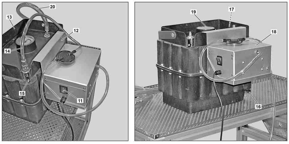
P20.00-2497-09
The tool kit of the electric vacuum pump (18) contains the bracket (12), hose (14), and electrical connection lines with the positive and negative terminals.
The tool kit of the NTKL adaptation (13) contains the hose (20) with a Y-distributor.
The drainage tank of the NTKL adaptation (13) must be empty before beginning work.
15 | Move switch (11) of electric vacuum pump (18) to "0" position. |
16 | Connect the positive and negative terminals of the electric vacuum pump (18) with a suitable 12 V voltage source (e.g. an on-board electrical system battery (G1)). |
Observe polarity of positive and negative terminals of electric vacuum pump (18). |
17 | Hook the bracket (12), as shown, into the NTKL adaptation (13). |
18 | Attach hose (14) to the NTKL adaptation (13). |
19 | Close off shutoff valves (15, 16, 17). |
20 | Connect hose (20) to the NTKL adaptation (13). |
21 | Remove Y-distributor from hose (20). |
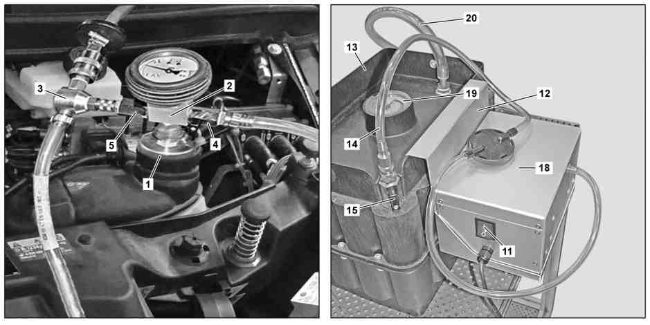
S20.00-A043-09
22 | Remove venturi nozzle (3) from the control unit (2). |
23 | Attach hose (20) to the control unit (2). |
Fasten the hose (20) to the connection fitting of the drain valve (5) with a suitable clamp. |
24 | Switch on electric vacuum pump (18). |
25 | Open stopcock (15). |
The feed valve (4) remains closed. |
The vacuum indicator (19) must indicate at least -0.9 bar. |
If -0.9 bar is not reached, |
|
Check cause, rectify it, and set up vacuum again. |
26 | Open drain valve (5) and evacuate entire engine cooling system for 5 minutes. |
While doing so, observe vacuum indicator (19). |
If vacuum does not remain stable, |
|
Check hoses, connections, and component parts of the engine cooling system, rectify causes, and repeat ventilation process and evacuation. |
Check
27 | drain valve (5). |
28 | Switch off electrical vacuum pump (18). |
29 | Remove hose (14) from NTKL adaptation (13). |
The vacuum in the NTKL adaptation (13) is disassembled as a result of this, until the vacuum indicator (19) displays 0.0 bar. |
30 | Based on the indicator of the control unit (2), check whether the vacuum remains stable for 30 s. |
If vacuum does not remain stable, |
|
Check hoses, connections, and component parts of the engine cooling system, rectify causes, and repeat ventilation process and evacuation. |
Filling
31 | Open feed valve (4). |
The engine cooling system is filled. |
The filling process ends when the indicator of the control unit (2) reaches 0.0 bar. |
32 | Open drain valve (5) as soon as coolant is no longer suctioned. |
The remaining existing vacuum will be removed in this way. |
33 | Remove control unit (2) with all connections. |
34 | Remove hose (20) from control unit (2). |
35 | Install Y-distributor on hose (20). |
Replace clamp. |
36 | Remove electric vacuum pump (18) from NTKL adaptation (13). |
37 | remove tester cap (1). |
38 | Correct coolant level on the engine cooling system expansion reservoir. |
The coolant level may not exceed the maximum marking. |
참조 문서
- ah2000p114201cw 냉각수 레벨 지침
- as2000z000101a 뜨거운 냉각수 분출 시 입은 화상에 의한 피부와 안구의 상해 위험 냉각수의 음용으로 인한 중독 위험