
S05.20-4504-09
1 | Belt pulley | 3 | Retaining pin | 5 | Markings | ||
2 | Intake camshaft | 4 | Camshaft bearing |

6 | Timing chain |
7 | Exhaust camshaft sprocket |
8 | Camshaft sprocket bolts at exhaust camshaft |
S05.20-4505-11
| Remove | ||
Caution | Risk of injury caused by scraping or cutting body parts on sharp vehicle parts | Always wear protective gloves when working on or near sharp and non-deburred vehicle parts. | |
1 | Remove cylinder head cover | ||
2 | Position piston of cylinder 1 to ignition TDC | Crank engine at crankshaft in direction of engine rotation and position belt pulley (1) as per marking. | |
Socket wrench bit | |||
3 | Check basic position of camshafts | Both markings (5) in camshaft sprockets must face each other and the markings of camshaft and camshaft bearing cap must be in alignment (arrows). Piston of cylinder 1 is at ignition TDC. | |
4 | Remove front cover at cylinder head | ||
5 | Mark timing chain (6) relative to exhaust camshaft sprocket (7) | For work that does not involve the rotation of the crankshaft, secure timing chain (6) with cable tie to exhaust camshaft sprocket (7); remove cable tie after installation. | |
6 | Remove exhaust camshaft sprocket (7) from exhaust camshaft | Remove camshaft sprocket bolts at exhaust camshaft (8) and remove exhaust camshaft sprocket (7) with mounted timing chain (6). | |
Installation: Replace camshaft sprocket bolts at exhaust camshaft (8). | |||
7 | Remove camshaft bearing cap | ||
Topical note | Marking on camshaft bearing caps | ||
Observe camshaft bearing cap marking. | |||
8 | Remove intake and exhaust camshafts | ||
| Install | ||
9 | Insert intake and exhaust camshafts | Oil the compensating elements and camshaft bearing points, check compensating elements for ease of movement. Align intake and exhaust camshafts at axial bearing. Mount camshafts so that both markings (5) are facing each other. | |
10 | Install camshaft bearing cap | ||
Topical note | Marking on camshaft bearing caps | ||
Observe camshaft bearing cap marking. | |||
11 | Position piston of cylinder 1 to ignition TDC | Crank engine at crankshaft in direction of engine rotation and position belt pulley (1) as per marking. | |
Socket wrench bit | |||
12 | Lock intake camshaft (2) | Slide retaining pin (3) at camshaft bearing (4) into bore in intake camshaft sprocket. | |
Retaining pins | |||
13 | Check basic position of camshafts | Both markings (5) in camshaft sprockets must face each other and the markings of camshaft and camshaft bearing cap must be in alignment (arrows). Piston of cylinder 1 is at ignition TDC. | |
14 | Mount exhaust camshaft sprocket (7) at exhaust camshaft | Mount exhaust camshaft sprocket (7) with mounted timing chain (6) and screw in camshaft sprocket bolts at exhaust camshaft (8). | |
Bolt, camshaft sprocket to exhaust camshaft | |||
15 | Remove retaining pin (3) | Retaining pins | |
16 | Install front cover at cylinder head | ||
17 | Crank engine at crankshaft in direction of engine rotation | At least two revolutions. | |
Socket wrench bit | |||
18 | Check basic position of camshafts | ||
If necessary: | |||
| |||
Set basic position of camshafts | |||
19 | Install cylinder head cover | ||
| Check | ||
Warning | Risk of accident from vehicle starting off by itself when engine running. Risk of injury (bruises and burns) resulting from working on the engine while it is being started or when it is running. | Secure vehicle to prevent it from starting off by itself. Wear closed and snug-fitting work clothes. Do not touch hot or rotating parts. | |
20 | Check for leak tightness with engine running |

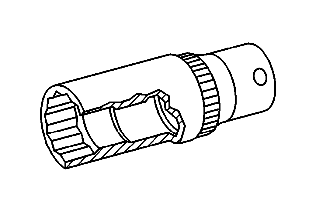
111 589 03 15 00
Retaining pins
001 589 65 09 00
Socket wrench bit
참조 문서
- ah0520p699204he 캠 샤프트-베어링 캡-식별코드
- ar0120s5014sd
- ar0130s5700sd
- ar0520s6010sd
- ar0520s6020sd
- ar0520s699204sd 캠샤프트 베어링 캡 탈, 장착
- as0000z000501a 엔진이 작동 중인 상태에서 급발진에 의한 사고 위험 시동 또는 구동 중인 엔진 근처에서 작업할 때 차량에 부딪히거나 열에 의한 상해 위험
- as0000z001701a 모서리가 날카로운 차량 부품에서 절단상과 찰과상으로 인한 상해 위험