
P01.10-2530-09
1 | Engine cover | 6 | Power steering expansion reservoir | 11 | Pressure connection fitting | ||
2 | Engine air intake duct | 7 | Power steering pressure line | 12 | Charge air duct | ||
3 | Brake booster vacuum line | 8 | Union nut | M16/6 | Throttle valve actuator | ||
4 | Fuel line | 9 | Power steering return line | Y58/1 | Purging switchover valve | ||
5 | Vacuum line | 10 | Screw/bolts |

P01.10-2531-09
7 | Power steering pressure line | 16 | Exhaust manifold with CAT | 20 | Range selector lever | ||
13 | Screw/bolt | 17 | Screw/bolts | A9 | Refrigerant compressor | ||
14 | Screw/bolts | 18 | Retaining clip | A9x1 | Refrigerant compressor connector | ||
15 | Underfloor catalytic converter | 19 | Shift rod |

P01.10-2532-09
21 | Bracket for oil lines | 24 | Radiator | 27 | Coolant hose | ||
22 | Automatic transmission oil line | 25 | Coolant hose | 28 | Coolant hose | ||
23 | Automatic transmission oil line | 26 | Coolant pipe on cylinder head | 29 | Coolant hose |

30 | Screw/bolt |
P01.10-2533-01
| Remove/install | ||
Danger ! | Risk of death caused by vehicle slipping or toppling off of the lifting platform. | Align vehicle between vehicle lift columns and position the four support plates at the vehicle lift support points specified by the vehicle manufacturer. | |
Danger ! | Risk of explosion caused by fuel igniting, risk of poisoning caused by inhaling and swallowing fuel as well as risk of injury to eyes and skin caused by contactwith fuel. | No fires, sparks, open flames or smoking. Pour fuels into suitable and appropriately marked containers only. | |
Danger ! | Risk of injury to skin and eyes suffering scalding from contact with hot coolantspray. Risk of poisoning from swallowing coolant. | Do not open cooling system unless coolant temperature is below 90 °C. Open cap slowly and release the pressure. Do not pour coolant into beverage containers. | |
Danger ! | Risk of explosion from explosive gas. Risk of poisoning and caustic burns from swallowing battery electrolyte. Risk of injury through burns to skin and eyes from battery acid or when handling damaged lead-acid batteries | No fires, sparks, open flames or smoking. Wear acid-resistant gloves, clothing and glasses. Only pour battery acid into suitable and appropriately marked containers. | |
1 | Detach ground line from battery | ||
| Notes on battery | ||
2 | Pull engine cover (1) upwards off cylinder head cover | When placing engine cover (1), ensure that seal is correctly seated at the oil filler neck. The seal should not be pressed down by the engine cover (1), but must lie against the engine cover (1). | |
3 | Remove engine air intake duct (2) | ||
4 | Remove wideband silencer | ||
5 | Remove poly-V belt | ||
6 | Remove fan shroud | ||
7 | Attach guard plate for radiator/condenser | ||
| Guard plate for radiator/condenser | ||
8 | Remove vacuum line (3) of brake booster | ||
9 | Relieve fuel pressure over diagnostic socket | ||
Pressure hose | |||
10 | Detach fuel line (4) from fuel distributor | Collect escaping fuel and seal connections with stop plugs. | |
Fuel feed line to fuel distributor | |||
Record plug | |||
11 | Detach vacuum line (5) from purging switchover valve (Y58/1) | ||
12 | Suction off oil out of power steering expansion reservoir (6) | Hand pump | |
13 | Detach pressure line (7) for power steering from power steering pump by unscrewing union nut (8) | Catch escaping oil with rags and close line connections with stop plugs. | |
Installation: Replace sealing ring. | |||
Connection fitting from high-pressure line to power steering pump | |||
Record plug | |||
14 | Detach return line (9) of power steering from expansion reservoir (6) for the power steering | Catch escaping oil with rags and close line connections with stop plugs. | |
Clamp, hydraulic line to power steering pump reservoir | |||
Record plug | |||
15 | Remove screw/bolts (10) and detach pressure connection (11) from throttle valve actuator (M16/6) | Screw/bolt, charge air duct downstream of charge air cooler to pressure damper | |
16 | Raise vehicle | ||
17 | Detach lower engine compartment paneling | ||
18 | Drain coolant at radiator | ||
19 | Drain engine oil | ||
| |||
Installation: Replace sealing ring. | |||
Oil drain screw to oil pan | |||
Engine oil | |||
20 | Detach engine wiring harness to remove engine | ||
21 | Detach charge air duct (12) from charge air cooler and take out with pressure connection (11) | ||
22 | Detach pressure line (7) of power steering from oil pan by unscrewing Screw/bolt (13) | Bolt, power steering oil line to oil pan | |
23 | Detach refrigerant compressor (A9) from timing case cover and engine support; to do this unscrew the screw/bolts (14) | Model 171 with engine 271 with transmission 722.6 | |
Disconnect refrigerant compressor connector (A9x1) and attach refrigerant compressor (A9) with connected pipe system, laterally at bottom of engine compartment. | |||
Bolt, refrigerant compressor to bracket | |||
Danger ! | Risk of injury. Skin or eye injuries may result when handling hot or glowing objects. | Wear protective gloves, protective clothing and safety glasses, if necessary. | |
24 | Detach underfloor catalytic converter (15) from exhaust manifold with catalytic converter (16); to do this unscrew screw/bolt (17) | Installation: Clean connecting points of combustion and corrosion residues; replace screw/bolts (17). | |
Bolt connecting underfloor catalytic converter to exhaust manifold with catalytic converter | |||
25 | Detach propeller shaft from output flange of automatic transmission | ||
Self-locking nut, flexible coupling to transmission or front propeller shaft | |||
26 | Detach retaining clip (18) and unhook shift rod (19) at range selector lever (20) | Installation: Replace retaining clip (18). | |
27 | Remove rear engine mount | ||
| 000 588 11 62 00 Major assembly mount | ||
After removing rear engine mount, lower transmission jack and allow automatic transmission to rest on the engine crossmember. | |||
28 | Detach bracket (21) for oil lines (22, 23) from automatic transmission | Bolt, dual clamp to oil line | |
29 | Detach oil line (22) for automatic transmission from radiator at bottom (24) | | |
Installation: Replace sealing ring. Ensure oil line (22) for automatic transmission is fitted correctly to the radiator (24). | |||
Record plug | |||
30 | Detach oil line (23) for automatic transmission from radiator at top (24) | | |
Installation: Replace sealing ring. Ensure oil line (23) for automatic transmission is fitted correctly to radiator (24). | |||
Record plug | |||
31 | Detach coolant hose (25) from coolant pipe (26) at cylinder head | Check condition of coolant hose (25). Replace it if necessary. | |
32 | Remove coolant hose (27) | Check condition of coolant hose (27). Replace it if necessary. | |
33 | Unclip coolant hose (28) from bracket and detach from coolant pipe (26) at cylinder head | Check condition of coolant hose (28). Replace it if necessary. | |
34 | Detach coolant hose (29) from connection fittings at cylinder crankcase | Check condition of coolant hose (29). Replace it if necessary. | |
35 | Detach both engine mounts from front axle carrier by unscrewing screw/bolts (30) | Screw/bolt, front engine mount to front axle carrier | |
36 | Lift out engine | | |
Slightly raise engine equally at front and back, pull slightly forward, then lower to the rear and lift out. | |||
Commercially available devices/tools | |||
37 | Install in the reverse order | ||
38 | Check oil level in automatic transmission, adjust to correct level if necessary | ||
39 | Fill power steering pump and bleed | ||
Danger ! | Risk of accident from vehicle starting off by itself when engine running. Risk of injury (bruises and burns) resulting from working on the engine while it is being started or when it is running. | Secure vehicle to prevent it from starting off by itself. Wear closed and snug-fitting work clothes. Do not touch hot or rotating parts. | |
40 | Carry out an engine test run | Check bolted connection for fuel line oil lines (22, 23) of the A/T, pressure and return line (7, 9) of the P/S, connections of the coolant hoses (25, 27, 28, 29), exhaust system, oil drain screw and coolant drain plug for leaktightness. |
Filling capacities for engine lubrication system |
Number | Designation | Engine 271 | Engine 271 | ||
BF18.00-P-1001-01L | Engine oil | Filling capacity without filter | Liter | – | – |
Filling capacity with filter | Liter | 5,5 | 5,5 | ||
Sheet | - | - | |||
Sheet | - | ||||
Sheet | - | ||||
Sheet | |||||
Sheet | - | ||||
Sheet | - | ||||
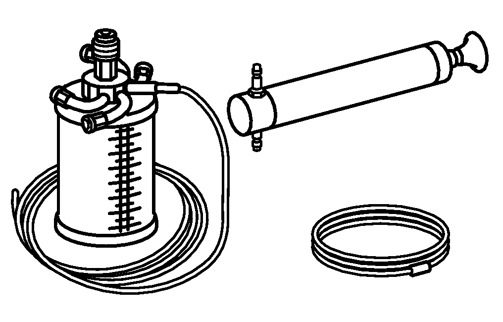


210 589 00 71 00
Hand pump
119 589 04 63 00
Pressure hose
129 589 00 91 00
Record plug
참조 문서
- ah5410p000101a
- ah5410p000101a 배터리 관련 지침
- ap1800p0101ab 엔진 오일 교환 및 오일 필터 교체
- ar0060p1000v 차량 들어 올리기, 정비대 위에 놓기
- ar0100p241002vc
- ar0703p146001v 서비스 밸브를 통해 연료압을 감압하십시오
- ar0941p6825v
- ar1322p1202v
- ar2000p1142v
- ar2040p6800vk
- ar2210p1160vk
- ar2700p0100ac 자동 변속기의 오일 레벨 점검, 필요한 경우 적절히 조절
- ar4110p005002v
- ar4310p0355v
- ar4630p0010v 파워 스티어링 펌프 주입 및 배기
- ar5410p0003v
- ar6120p1105v
- as0000z000201a 뜨겁거나 달아오른 물체를 취급할 때 피부와 눈에 입을 수 있는 상해 위험
- as0000z000501a 엔진이 작동 중인 상태에서 급발진에 의한 사고 위험 시동 또는 구동 중인 엔진 근처에서 작업할 때 차량에 부딪히거나 열에 의한 상해 위험
- as0000z001001a 리프터에서 차량이 미끄러지거나 틸팅 시 생명의 위험
- as2000z000101a 뜨거운 냉각수 분출 시 입은 화상에 의한 피부와 안구의 상해 위험 냉각수의 음용으로 인한 중독 위험
- as4700z000101a 인화에 의한 폭발 위험, 연료의 흡입 및 음용에 의한 중독 위험, 연료의 피부 및 안구 접촉에 의한 상해 위험
- as5410z000101a 단락 및 폭발성 기체 유출로 인한 화재/폭발 위험 배터리 전해액/증기, 단락 및 전기 아크에 노출 시 눈, 피부, 점막의 부식으로 인한 화상/상 해 위험 배터리 전해액을 삼키거나 피부
- wf5850p011001a
- ws0100p0092b