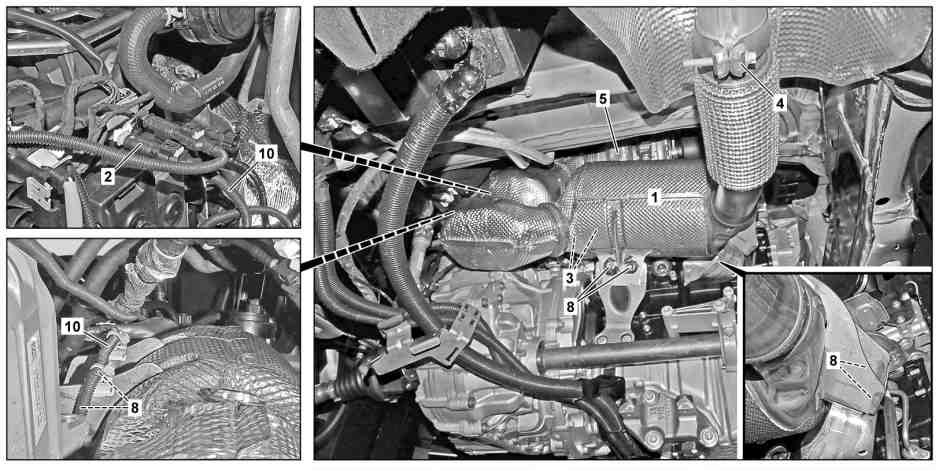
D49.20-0033-09
1 | Exhaust aftertreatment unit | 3 | Lines | 8 | Bolts | ||
2 | Electrical connector | 5 | Clip | 10 | Electrical wiring harness |
Danger | Risk of death caused by vehicle slipping or toppling off of the lifting platform. | Align vehicle between vehicle lift columns and position the four support plates at the vehicle lift support points specified by the vehicle manufacturer. | |
Warning | Risk of burn injuries, suffocation and poisoning when working on the exhaust system and the components connected to it. Risk of suffocation and risk of poisoning caused by inhalation of gaseous and solid components of the exhaust. Risk of poisoning caused by skin contact with solid components of the exhaust. | Wear protective clothing and safety glasses. Use the extraction system. Move people out of the hazard area. | |
Warning | Risk of injury. Moving parts can pinch, crush or, in extreme cases even sever extremities. | No parts of the body or limbs should be within the operating area of mechanical components when moving components. | |
Warning | Risk of injury. Skin or eye injuries may result when handling hot or glowing objects. | Wear protective gloves, protective clothing and safety glasses, if necessary. | |
Topical note | Information on preventing damage to electronic components due to electrostatic discharge | ||
Topical note | Notes on avoiding damage through contamination and foreign objects | ||
Topical note | Notes on self-locking nuts and bolts | ||
Topical note | Notes on threaded connections fastened using a tightening angle-based tightening process | ||
Topical note | Notes on carrying out repair work in the vehicle interior | ||
Notes on repair work on suspension components | |||
Note on calculation of tightening torque when using insertion or socket tools with various effective lengths | |||
| Remove | ||
1 | Fix steering wheel in center position. | ||
Retainer device | |||
Tensioning nut | |||
2 | Remove NOx sensor with control unit upstream of SCR catalytic converter from exhaust gas aftertreatment unit (1). | ||
3 | Remove temperature sensor of diesel particulate filter from exhaust gas aftertreatment unit (1). | ||
Do not disconnect electrical connector. | |||
4 | Remove lambda sensor upstream of catalytic converter from exhaust gas aftertreatment unit (1). | ||
5 | Disconnect electrical connection (2). | ||
6 | Remove differential pressure sensor from bracket. | ||
Do not remove lines (3) from differential pressure sensor. | |||
7 | Remove electrical wiring harness (10) from bracket. | Position electrical wiring harness (10) outside of working area. | |
8 | Remove front wheel and tire assembly. | ||
9 | Remove lower engine compartment paneling |
| |
10.1 | Remove rear muffler. | Engine 651 in model 910 | |
10.2 | Remove SCR catalytic converter downstream of exhaust gas aftertreatment unit (1). | Engine 651 in model 910 | |
11 | Secure vehicle on vehicle lift. | ||
Commercially available devices/tools | |||
12 | Remove, support and lower front axle carrier. | ||
| 000 588 11 62 00 Major assembly mount | ||
| 000 588 10 62 00 Support plate | ||
| |||
Commercially available devices/tools | |||
13 | Remove AdBlue® metering valve from exhaust gas aftertreatment unit (1). | ||
Do not disconnect electrical connector and lines. | |||
14 | Remove NOx sensor with control unit downstream of diesel particulate filter from exhaust gas aftertreatment unit (1). | ||
15 | Carefully push engine by hand forwards and support with major assembly mount. | ||
| 000 588 11 62 00 Major assembly mount | ||
| 000 588 10 62 00 Support plate | ||
16 | Remove clamp (5). | WIS Service Media | |
17 | Remove exhaust gas aftertreatment unit(1). | To do so, remove screws (8). Dispose of seal between exhaust gas turbocharger and exhaust gas aftertreatment unit (1). | |
The exhaust gas aftertreatment unit (1) comprises the diesel particulate filter and SCR catalytic converter. | |||
18 | Disassemble exhaust gas aftertreatment unit (1). | If diesel particulate filter and/or SCR catalytic converter of exhaust gas aftertreatment unit (1) will be replaced. | |
Assembly tool | |||
| Install | ||
19 | Assemble exhaust gas aftertreatment unit (1). | If diesel particulate filter and/or SCR catalytic converter of exhaust gas aftertreatment unit (1) will be replaced. | |
Clamp, SCR catalytic converter to diesel particulate filter | |||
Screw, diesel particulate filter holder to SCR catalytic converter holder | |||
Assembly tool | |||
20 | Position exhaust gas aftertreatment unit (1) in installation position. | Replace seal between exhaust gas turbocharger and exhaust gas aftertreatment unit (1). | |
WIS Service Media | |||
21 | Install clamp (5). | Do not yet tighten clamp (5). | |
22 | Slightly screw in screws (8) by hand. | Do not yet tighten screws (8). | |
23 | Tighten clamp (5). | Clamp, exhaust gas aftertreatment unit to exhaust gas turbocharger | |
24 | Tighten screws (8) at right bracket of diesel particulate filter of exhaust gas aftertreatment unit (1). | Screw, exhaust gas aftertreatment unit to holder | |
25 | Tighten screws (8) at left bracket of SCR catalytic converter of exhaust gas aftertreatment unit (1). | Screw, exhaust gas aftertreatment unit to holder | |
26 | Tighten screws (8) at center bracket of diesel particulate filter of exhaust gas aftertreatment unit (1). | Screw, exhaust gas aftertreatment unit to holder | |
27 | Remove tools for engine support. | ||
| 000 588 11 62 00 Major assembly mount | ||
| 000 588 10 62 00 Support plate | ||
28 | Install NOx sensor with control unit downstream of diesel particulate filter at exhaust gas aftertreatment unit (1). | ||
29 | Install AdBlue® metering valve at exhaust gas aftertreatment unit (1). | ||
30 | Install front axle carrier. | ||
| 000 588 11 62 00 Major assembly mount | ||
| 000 588 10 62 00 Support plate | ||
Commercially available devices/tools | |||
Screw/bolt, engine stabilizer mount to front axle carrier | |||
Nut, torsion bar linkage to stabilizer bar | |||
Front bolt, front axle carrier to body | |||
Rear bolt, front axle carrier to body | |||
Screw, lower steering shaft to steering gear | |||
31 | Remove retainer of vehicle at vehicle lift. | ||
32.1 | Install rear muffler. | Engine 651 in model 910 | |
Engine 651 in model 910 | |||
32.2 | Install SCR catalytic converter downstream of exhaust gas aftertreatment unit (1). | Engine 651 in model 910 | |
Engine 651 in model 910 | |||
33 | Install front wheel and tire assemblies. | ||
34 | Install electrical wiring harness (10) at bracket. | ||
35 | Install differential pressure sensor at bracket. | ||
36 | Connect electrical connector (2). | ||
37 | Install lambda sensor upstream of catalytic converter at exhaust gas aftertreatment unit (1). | ||
38 | Install temperature sensor of diesel particulate filter at exhaust gas aftertreatment unit (1). | ||
39 | Install NOx sensor with control unit upstream of SCR catalytic converter at exhaust gas aftertreatment unit (1). | ||
40 | Remove securing of steering wheel. | ||
Retainer device | |||
Tensioning nut | |||
41 | Perform initialization of exhaust gas aftertreatment unit (1) with vehicle diagnosis system. | If diesel particulate filter and/or SCR catalytic converter of exhaust gas aftertreatment unit (1) were replaced. | |
| Connect/disconnect diagnostic unit | ||
| Check | ||
Warning | Risk of accident from vehicle starting off by itself when engine running. Risk of injury (bruises and burns) resulting from working on the engine while it is being started or when it is running. | Secure vehicle to prevent it from starting off by itself. Wear closed and snug-fitting work clothes. Do not touch hot or rotating parts. | |
42 | Perform engine test run and check exhaust system in terms of leak tightness. | ||
43 | Install underbody paneling. |
| |
44 | Install lower engine compartment lining. |
|


651 589 13 63 00
Assembly tool
906 589 00 21 00
Tensioning nut
129 589 01 21 00
Retainer device
参照文書
- ad0000d200006ts
- ah0000n000101a セルフロッキング·ナットおよびボルトに関する注意事項
- ah0000p001501cw 異なる作用長の差込み、接続用ツールを使用する場合の 締付けトルク算出のための注意事項
- ah0000p002001a 回転角度で調整する締付法にしたがい作られたボルト接続部の注意事項
- ah0000p010001a シャーシ構成部品のリペア作業に関する注意事項
- ah0000p500001a 汚れおよび異物による損傷防止に関する注意事項
- ah5400p000101a 静電気放電による電子構成部品の損傷を防ぐための注意事項
- ah6800n000101s 車内でリペア作業を行う際の注意事項
- ar0060d010001ts
- ar0704d0005tsf
- ar0704d0025tsf
- ar0704d0086tsf
- ar3310d000103tsf
- ar4010d1100ts
- ar4620d050001ts
- ar4910d4952tsf
- ar4920d001801tsf
- ar4920d2000tsf
- ar4920d2060tsf
- ar4920d2063tsf
- ar4920d8121tsf
- ar6120d1105ts
- ar6130d1001ts
- as0000z000201a 高温になっているか、あるいは赤熱している部品を取り扱う場合に、火傷を負うあるいは失明する危険があります。
- as0000z000501a エンジン作動中に車両がひとりでに動き出す危険があります。 スタート時または作動中のエンジンに接触すると、巻き込まれて負傷をする、または火傷をする危険があります。
- as0000z000901a 手指をはさまれたり、締め付けられて負傷する危険があります。注意をおこたると、メカニズムに巻き込まれて、手指が切断される危険もあります。
- as0000z001001a 車両がリフトから滑り落ちたり、傾くことによる生命の危険
- as4900z000101a エグゾースト・システムおよび接続している構成部品での作業 では、火傷、窒息、および中毒の危険があります。 排気ガスの気体および固体の成分を吸い込むことによる窒息 �
- ws0100p0092b 000 588 11 62 00 ユニット・マウント
- ws2600p3309b 000 588 10 62 00 マウント・プレート