09-6263 Dismantling and assembling turbocharger
Preceding work: Removing turbocharger (09-6030) and (09-6620), respectively. |
|

1 Compressor housing | check for signs of damage; polish slight traces of rubbing smooth with fine sandpaper. If severe damage exists as a result of foreign bodies or compressor wheel, replace compressor housing. |
2 Tensioning segment | |
3 Hexagon bolts | 10 Nm. |
4 Locking nut | oil, (KKK turbocharger 5 Nm, turbocharger T 45, 15 Nm). |
5 Compressor wheel | check for signs or rubbing, cracks and rough surface; replace if necessary. |
6 O-ring | replace. |
7 Compressor rear wall | check for rough surface, replace if necessary. |
8 Washers | |
9 Hexagon bolts | 10 Nm. |
10 O-ring | replace. |
11 Piston rings | check for signs of wear, oil lightly, install 90° offset to oil feed and drain holes. |
12 Hexagon bolts | 5 Nm. |
13 Axial washer | replace, oil lightly. |
14 Sealing bush | check piston ring grooves for signs of wear, replace if necessary. |
15 Bearing collar | check for smooth surface, replace if necessary, oil lightly before installing. |
16 Bearing bushes | replace, oil lightly. |
17 Circlip | install with rounded side facing bearing bush. |
18 Bearing housing | check bearing bores for signs of wear, replace if necessary. |
19 Heat shield | check for signs of bending, cracking and rough surface, replace if necessary. |
20 Sealing bush | check piston ring grooves for signs of wear, replace if necessary. |
21 Piston ring | check for signs of wear, oil lightly. |
22 Bearing disc | |
23 Bush | |
24 Oil deflector | |
25 Axial bearing washer | replace, oil lightly. |
26 Bearing collar | |
27 Piston ring | check for signs of wear, oil lightly. |
28 Turbine wheel with shaft | remove deposits, check for broken, bent vanes and cracking, check bearing points for signs of wear, ring groove for wear, replace turbine wheel if necessary. Check concentricity 0.007 mm, dial gauge 001 589 53 21 00, measuring instrument 363 589 02 21 00. |
29 Tensioning strap | coat thread with copper paste. |
30 Hexagon nut | 20 Nm. |
31 Turbine housing | check shape tolerance of connection bore, check for rough surface, cracking and signs of rubbing, polish light signs of rubbing smooth with fine sandpaper. If severe damage as a result of foreign bodies or compressor wheel, replace. |
32 Hexagon bolt | 20 Nm. |
33 Tensioning segment | |
34 Turbine housing | check shape tolerance of connection bore, check for rough surface, cracking and signs of rubbing, polish light signs of rubbing smooth with fine sandpaper. If severe damage as a result of foreign bodies or compressor wheel, replace. |
35 Piston rings | check for signs of wear, oil lightly. |

Sectional view
KKK turbocharger
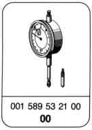

Special tools
Commercially available tools
Hot air fan | Leister Gibli 2 | e. g. make Karl Leister CH-6056 Kägiswil |
Insert | Order number: 1/991-6 | e. g. make Hazet 5630 Remscheid |
See also Workshop Equipment Manual!
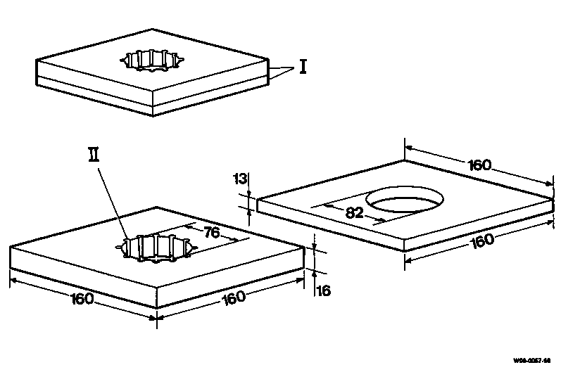
Shop-made tool
Holding device for T45 turbocharger
I Bolted
II 11 holes 9.5 dia.

Clamping jaws for KKK turbocharger
A Knurling
B Fitted into existing rotor

Disassembling
-------------------------------
1 Clamp turbocharger in vice.
Note
Use protective jaws.
2 T 45 turbocharger:
2.1 Unscrew hexagon nut (30) from tensioning strap (29) and take off tensioning strap.

2.2 Mark position of turbine housing (31) relative to bearing housing (18) (arrow).
Remaining removal as from step 4.

3 KKK turbocharger:
3.1 Mark position of turbine housing (34) relative to bearing housing (18) (arrow).
3.2 Take tensioning segments (33) off turbine housing (34).

4 Carefully take turbine housing off bearing housing.
Note
Pay attention to the vanes of the turbocharger shaft when taking off turbine housing.

5 Mark position of compressor housing (1) relative to compressor rear wall (7) (arrow).

6 Take tensioning segments (2) off compressor housing.

7 Use a soft hammer to carefully detach compressor housing (1) from bearing housing and take off turbine housing.
Note
Pay attention to the vanes of the compressor wheel when taking off the compressor housing.

8 Clamp holding device (36) into the vice and insert bearing housing with turbine wheel.
Note
Use holding device or clamping jaws depending on the type of turbocharger.
9 Take off O-ring (6).

10 Unscrew shaft nut with T wrench.
Note
When slackening shaft nut, ensure that the turbine wheel shaft is not damaged. Use T wrench so that no bending torques act on the shaft.

11 Heat compressor wheel (5) radially with hot air fan and take off.

12 Carefully take bearing housing together with compressor rear wall off the rotor shaft.

13 Center heat shield (19) and take off from the rotor shaft.
Note
Pay attention to piston ring on the turbine wheel shaft.

14 Take piston ring (27) off the turbine wheel shaft.
Note
Remove two piston rings from KKK turbocharger.

15 Take off compressor rear wall (7).

16 KKK turbocharger:
16.1 Remove O-ring (10), sealing bush (20) and piston ring (21) from the compressor rear wall (7).

16.2 Remove bearing disc (22), oil deflector (24), bush (23), axial bearing disc (25) and bearing collar (26).

16.3 Remove circlips (17) and bearing bush (16).
Remaining removal is performed as from step18.

17 T 45 turbocharger:
17.1 Take off sealing bush (14) and remove piston rings (11) from the sealing bush.
17.2 Take off O-ring (10).

17.3 Unscrew hexagon bolts (12) from the bearing housing, take off axial disc (13) and bearing collar (15).

17.4 Take out bearing bush (16) and remove circlip (17).

18 Turn bearing housing, remove circlips (17) and bearing bush (16).
Assembling
-------------------------------
Note
- Clean all parts thoroughly in acid-free solution using a brush. Remove combustion residues with plastic scraper.
- Check turbine and compressor housings for signs of rubbing. If slight damage exists, polish traces of rubbing with fine sandpaper. If severe damage exists, replace parts.
- Check compressor and turbine wheels for signs of cracking, rubbing, broken and bent vanes.
- Check piston ring groove in turbine wheel shaft for signs of wear.
- Check bearing points in bearing housing for signs of wear.
- Check rear wall for smooth surface.
- Check bearing collar for smooth surface.
- Check piston ring grooves in sealing bush for signs of wear.
- Check piston rings for signs of wear.

1 Checking concentricity of rotor shaft:
Clamp rotor shaft between two prisms. Attach dial gauge
20 mm away from end of rotor shaft. Rotate rotor shaft and observe deflection of dial gauge pointer.
Permissible deflection 0.007 mm.
If deflection is greater, replace the rotor shaft.
Dial gauge 001 589 53 21 00
Dial gauge holder 363 589 02 21 00
2 Install circlips (17) and bearing bush (16) (oil lightly) from the turbine side into the bearing housing.
Note
The circlips should be inserted in such a way that the rounded side is facing the bearing bush.
3 T 45 turbocharger:
3.1 Install circlip (17) into the bearing housing from the compressor side.
Note
The circlip should be inserted in such a way that the rounded side is facing the bearing bush.
3.2 Lightly oil bearing bush (16) and insert into the bearing housing.

3.3 Lightly oil bearing collar (15) and new axial bearing disc (13).
3.4 Fit bearing collar into the axial bearing disc and place into the bearing housing.

3.5 Screw hexagon bolts (12) tight, 5 Nm.

3.6 Lightly oil new O-ring (10) and insert into the groove of the bearing housing.
Remaining installation is performed as from step 5.
4 KKK turbocharger:
4.1 Install circlips (17) and bearing bush (16) (oil lightly) from the compressor side into the bearing housing.
Note
The circlips should be inserted in such a way that the rounded side is facing the bearing bush.

4.2 Insert bearing collar (26).
4.3 Install new axial bearing disc (25).
Note
Pay attention to centering pins (arrows).
4.4 Install bush (23), oil deflector (24) and bearing disc (22).
4.5 Install piston ring (21) onto the sealing bush (20) and insert into the compressor rear wall (7).
4.6 Grease O-ring (10) with brake cylinder paste and insert into the compressor rear wall (7).
5 Install compressor rear wall (7), 10 Nm.

6 T 45 turbocharger:
6.1 Lightly oil sealing bush (14) and piston rings (11).
6.2 Fit piston rings - offset 180° to each other - onto the sealing bush.
6.3 Carefully insert sealing bush into the compressor rear wall; when doing this, compress the two piston rings one after the other.
Note
The flange faces for the oil feed and oil return lines must be positioned 90° offset to the respective piston ring gap.

7 Clamp holding device or clamping jaws and insert turbine wheel (28).
Note
Use holding device or clamping jaws depending on the type of turbocharger.
8 Lightly oil piston ring (27) and carefully fit onto the turbine wheel shaft.
Note
If turbine wheel has two piston rings, install piston rings offset 180°.

9 Center piston ring (27) on the turbine wheel shaft.
10 Carefully place heat shield (19) over the piston ring onto the turbine wheel.
11 Oil bearing seats and piston ring of turbine wheel shaft.
12 Carefully fit preassembled bearing housing over the turbine wheel shaft.

13 Heat compressor wheel (5) with a hot plate to 130 °C.

14 Push compressor wheel onto the turbine shaft.
15 Lightly oil threaded piece of turbine shaft and hexagon nut (4) and screw on.

16 Screw hexagon nut tight with T torque wrench, 5 Nm.

17 Lightly oil new O-ring (6) and fit onto the shoulder of the compressor rear wall.
18 Clamp compressor housing (1) in vice, fit on bearing housing with compressor rear wall (7) and align to the marking (arrow).
19 Fit on tensioning segments (2) and screw tight, 10 Nm and 15 Nm, respectively.

20 T 45 turbocharger:
20.1 Coat thread (arrow) of tensioning bolt (29) with copper paste. Place tensioning strap (29) onto the bearing housing.
20.2 Fit on turbine housing (31).
20.3 Align turbine housing (31) and bearing housing (18) to the marking (arrow).
20.4 Screw tensioning strap (29) tight with hexagon nut (30), 20 Nm.
20.5 Slacken hexagon nut (30) again and screw tight,
20 Nm.
21 KKK turbocharger:
21.1 Fit on turbine housing (34).
21.2 Align turbine housing (34) and bearing housing (18) to the marking (arrow).
21.3 Screw tensioning segments (33) tight, 20 Nm.
22 Check that turbocharger shaft rotates freely.
23 Before operating turbocharger, pour engine oil through the oil feed hole into the bearing housing.
Note
If the turbocharger is not installed immediately, seal all openings on the turbocharger with siutable caps.
Referenced documents
- bb0040p022302a Specified engine oils for Cars, Vans (service) - Overview
- ra00005010002x 0002 - General: Engine model designations Engines OM 441-443 LA, EURO I
- ra00005010004x 0004 - General: Special tools Engines OM 441-443 LA, EURO I
- ra00005010005x 0005 - General: Technical data Engines OM 441-443 LA, EURO I
- ra00005010010x 0010 - General: Tightening torques Engines OM 441-443 LA, EURO I
- ra00005010901x 0901 - Repair of tapped holes using Heli-Coil inserts Engines OM 441-443 LA, EURO I
- ra09005016010x 6010 - Testing the turbocharger, determining the condition, fault diagnosis Engines OM 441-443 LA, EURO I
- ra09005016030x 6030 - Removal and installation of the turbocharger Engines OM 441-443 LA, EURO I