AR60.80-B-0095C | Check tension of cab mounting torsion bar, adjust | 12.02.16 |
Body 693.860 with Vehicle 693.154, 693.196
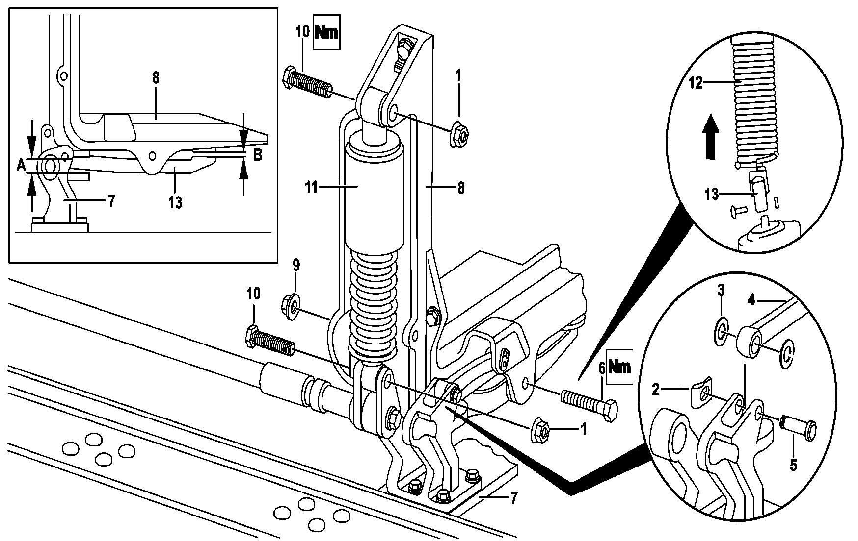
B60.80-0017-09

B60.80-0039-06
1 Nut
2 Safety clip
3 Washers
4 Lever
5 Pivot pin
6 Screw
7 Stand support
8 Cabin Bearing Bracket
9 Nut
10 Screw
11 Tors. Vibration Absorber
12 Protective bellows
13 Crosshead joints
14 Nut
15 Gasket seal
16 Washer
17 Eccentric washer
18 Washer
19 Screw
20 Screw
21 Cabin Stabilizer
22 Frame rail
| Remove and install | ||
| Indications regarding screws and self-locking nuts | ||
1 | Open the front end cover | ||
2 | Remove front bumper face bar | ||
3 | Remove the protective bellow (12) between the intake line and air cleaner box | ||
4 | Release the protective bellows (12) of the steering box and move it up | ||
5 | Remove the crosshead joints (13) to the control arm shaft | Install: The fixing groove of crosshead joint to the control arm shaft should coincide with the marking of the steering worm shaft. | |
| |||
6 | Adjust the length of the arms in the suspension device according to the roof height | ||
7 | Remove the safety clip (2), remove the pivot pin (5), and remove the lever (4) to the bearing stand and turn it up | ||
Danger! | Risk of injury due to becoming trapped and crushed while cab is being tilted | During tilting the cab forward and backward, do not get into the slope area and take preventive measures to prevent the entry of unauthorized persons. Always tilt the cab until its final position and lock it with the safety device. | |
8 | Tilt the cabin | ||
| Directions on cab tilting | ||
9 | Check if the front cab suspension is tension free | The Cabin stand(8) should not rest on the setting surfaces, both in the front and in the rear. A free space should be maintained for (A) and (B). | |
In case one of the surfaces of the cab suspension is set: Raise the cabin with the suspension device and lower it. | |||
10 | The upper suspension of the tilting cylinder must show some gap | Check if the tilting cylinder has no pressure. | |
11 | Remove the screws (6) from the cabin stand(8) | | |
12 | Remove the nuts (1) from the Tors. Vibration Absorber (11) suspension | | |
| |||
13 | Remove the Tors. Vibration Absorber (11) | Raise the cabin with the suspension device until it is possible to remove the screws (10). | |
14 | Remove the cabin Stabilizer (21) from the cabin bearing bracket(8) | ||
15 | Remove the nuts (14) from the screws (20) and remove the bearing stand (8) | | |
16 | Remove the cabin Stabilizer (21) fully with the support of the stand (7) | ||
17 | Remove the stand mounts (7) from the cab stabilizer (21) | | |
18 | Examine the stabilizer bushings and replace if necessary | ||
Extractor device | |||
19 | Install in reverse order |
Steering shaft
Número | Denominação | Chassis 384, 386, 388, 397, 660, 682, 688, 693, 694, 695, 696 | |||
BA46.10-B-1001-01A | Steering column cross bar | M8 | Nm | 30...35 | |
M10 | Nm | 60 | |||
Cab, cab mounting
Número | Denominação | Chassis 693.1 with Cabin 693.860/861 | |||
BA60.80-B-1001-01B | Stabilizer bolt in the cabin front suspension | M16x1.5 | Nm | 248 | |
BA60.80-B-1002-01B | Upper nut for the front telescopic feet in the cabin front suspension | M14x1.5 | Nm | 163 | |
BA60.80-B-1003-01B | Lower nut of the frontal telescopic feet in the stabilizer | M14x1.5 | Nm | 163 | |
BA60.80-B-1004-01B | Front bearings brackets nuts in the rail | M16x1.5 | Nm | 225 | |
BA60.80-B-1005-01B | Stabilizer bolts in the front bearings brackets | M14x1.5 | Nm | 163 | |

950 589 00 33 00
Extractor device
Referenced documents
- ah0000b000101a Notes on self-locking nuts and bolts
- ah6080b000301a Notes on tilting the cab
- ar6080b002001a Remove, install bearing bushes at anti-roll bar of cab mounting
- ar8820b2000g Remove/install front bumper
- as6080b000101a Risk of injury caused by body parts being pinched or crushed as cab is tilted