AR32.22-D-7000A | Checking and adjusting vehicle level | 21.6.96 |
MODEL 668, 670 with CODE (CE2) Air suspension at rear
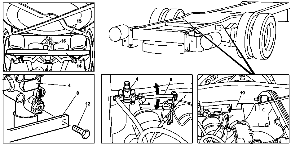
D32.22-0008-09
Shown: left-hand side of vehicle, right-hand side is the same.
4 Height control valve
7 Height control valve actuating rod
8 Actuating lever
10 Spacer block for level adjustment
12 Mounting bolt for actuating lever
14 Bellows cross member
15 Overhang cross member
16 Checking dimension
| Checking | ||
1 | Measure checking dimension (16) in the center of the vehicle between upper edge of bellows cross member (14) and lower edge of overhang cross member (15). | Brief check: This dimension is used for a rough check of the vehicle level. | |
2 | Measure distance between upper edge of axle tube and lower edge of frame longitudinal member on the left and right side of the vehicle. | The level is to be adjusted if there are deviations from the specified dimensions (work steps 3 to 10). | |
Adjusting | |||
3 | Unscrew actuating rods (7) from the actuating levers (8). | ||
4 | Move vehicle frame into the highest position by operating the levers (8). | ||
5 | Install spacer blocks (10) on the left and right between the axle tube and frame longitudinal member. | ||
| Spacer block for vehicle level adjustment | Models 668, 670 with CODE CE2 (rear air suspension) | |
6 | Lower frame onto the spacer blocks (10) by operating the lever (8). | Ensure that the frame contacts the two spacer blocks evenly. | |
7 | Pin height control valves in the zero position. | To do this, insert 4 mm dia. cotter pin driver in the bore in the top of the shaft and align between the two lugs (arrow). | |
8 | Adjust length of actuating rods (7) so that they can be installed without any play. | ||
9 | Screw on actuating rods (7). | ||
10 | Fix length of actuating rods (7) by carefully tightening the lock nuts. | ||
10 | Jack up the vehicle frame at the rear until the spacer blocks (10) can be removed. | Secure vehicle to prevent it from rolling away. | |
11 | Remove spacer blocks (10). | ||
12 | Recheck vehicle level. |
Test values of vehicle level at rear axle
Number | Designation | Models 668, 670 with CODE CE2 | |
BE40.20-N-1001-03A | Distance between axle tube and bottom edge of frame | mm | 953 |
BE40.20-N-1002-03A | Distance between top edge of bellows cross member and bottom edge of overhand cross member | mm | 2265 |
Commercially available tools
Referenced documents
- wf5850n322201a Spacer block for vehicle level adjustment