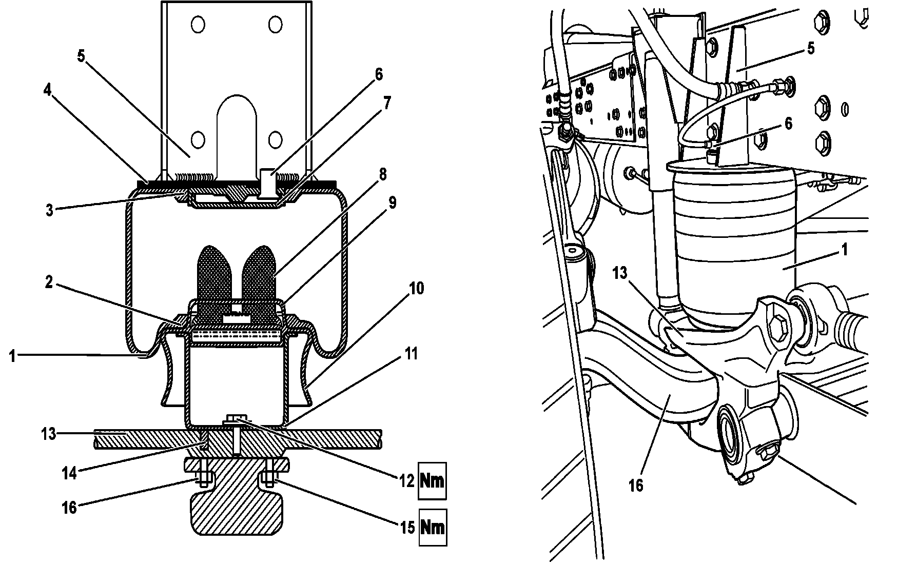
B32.22-0002-09
Front axle |
1 | Pneumatic suspension bellows | 9 | Sealing edge of the bellows support plate | |
2 | Bottom sealing edge of the bellows | 10 | Support plate | |
3 | Upper sealing edge of the bellows | 11 | Lower cylindrical support | |
4 | Top bracket (integrated to the frame) | 12 | Flanged screw | |
5 | Vehicle frame | 13 | Pneumatic bellows bracket | |
6 | Threaded nozzle of the pneumatic connection | 14 | Guide pin | |
7 | Top sealing ring | 15 | Fastening screws | |
8 | Support stop | 16 | Axle |

B32.22-0001-09
Rear axle |
1 | Pneumatic suspension bellows | 8 | Support stop | |
2 | Bottom sealing edge of the bellows | 9 | Sealing edge of the bellows support plate | |
3 | Upper sealing edge of the bellows | 10 | Support plate | |
4 | Top bracket (integrated to the frame) | 11 | Lower cylindrical support | |
5 | Vehicle frame | 12 | Flanged screw | |
6 | Threaded nozzle of the pneumatic connection | 13 | Pneumatic bellows bracket | |
7 | Top sealing ring | 14 | Guide pin |
| Remove | ||
Danger | Risk of death caused by vehicle slipping or toppling off of the lifting platform. | Align vehicle between vehicle lift columns and position the four support plates at the vehicle lift support points specified by the vehicle manufacturer. | |
Danger | Risk of death from lowering vehicle when working between wheels and body. Risk of injury from pinching or crushing when working on the air suspension. | Testing and repair work between the wheel and wheel arch or in the wheel well should only be performed if the vehicle is secured using suitable support fixtures to prevent it from lowering. | |
1 | Lift the vehicle and supports it from the frame | Chock the vehicle so that it cannot move. | |
2 | Remove the wheels |
| |
3 | Remove the dampers | Remove/install front shock absorber | |
Remove/install rear shock absorber. | |||
This procedure makes easier accessing and moving the axle | |||
Excess stroke of the dampers can lead to serious damage thereto. | |||
4 | Completely depressurize the pneumatic bellows | ||
5 | Remove the compressed air line from the threaded nozzle (6) | ||
6 | Remove the pneumatic bellows (1) and the support plate (10) | Do not use levers or metal tools. As a last resort, use a wooden lever with rounded tips. | |
Manually disengage the bellows (1) from the upper ring sealing edge on the bracket (9) with due care, and remove it together with the lower support plate (10). | |||
7 | Remove the pneumatic bellows (1) from the support plate (10) | ||
8 | Release the screw (12) and remove the cylindrical bracket (11), detaching the pneumatic bellows (13) from the bracket | ||
9 | Remove the stop (8) from the support plate (10) | Secure the assembly from the support plate (10) on a vice (with protected jaws) and use an appropriate lever without damaging the sealing edges. | |
| Clean | ||
10 | Clean all mechanical components and the support and bellows surfaces | The bellows should be dry cleaned without using any cleaning fluid or solvent. | |
Clean the sealing areas on the supporting metal parts and the sealing edges of the bellows. | |||
| Check | ||
11 | Check the lower (2) and top (3) sealing edges and the support plate (10) for damage | If necessary, replace the support plate or the top bracket | |
12 | Check the condition of the pneumatic bellows (1) and the inner stop (8) | ||
| Leaf springs/air bellows - visual inspection for damage | . | |
For the functionality purposes, replace the bellows in pairs. | |||
| Install | ||
13 | Install the bellows support bracket (13) on the axle | Only in case of removal. | |
14 | Install the cylindrical bracket (11) on the pneumatic bellows bracket (13), and tighten the flanged screw (12) | Tighten the screw (12) from the inside. | |
.Bellows cylindrical support bolt | |||
15 | Press the stop (8) on the support plate (10) | Lubricate the stop with the prepared and specified glycerin soap. After mounting, remove any lubricant residues around the components. | |
Lubricant | |||
16 | Mount the pneumatic bellows (1) on the support plate (10) | Slightly lubricate all contact parts of the bellows with prepared glycerin soap. | |
Lubricant | |||
17 | Install the assembly (pneumatic bellows and support plate) on the lower cylindrical bracket (11) | ||
18 | Fit the sealing edge (3) of the pneumatic bellows (1) in the upper sealing ring (7) of the top bracket (4) | The full fitting in the top bracket (4) occurs upon pressurization of the bellows. | |
19 | Install the wheel | Remove/install wheels | |
20 | Lower the vehicle | ||
21 | Pressurize the pneumatic system | ||
22 | Check for potential pressure leaks in the system | Use neutral glycerin soap foam. Do not use regular soap foam because it contains caustic soda, which corrodes the materials. | |
23 | Run a test drive | Check the air suspension behavior. |
Referenced documents
- ap3220b3255a Leaf springs/air bellows - visual inspection for damage
- ar3225b0105xb Remove/install front shock absorber
- ar3225b0110xa Remove/install rear shock absorber
- ar4010b1101a Remove/install wheels
- as0000z001001a Risk of death caused by vehicle slipping or toppling off of the lifting platform.
- as3222z000101a Risk of death from lowering vehicle when working between wheels and body. Risk of injury from pinching or crushing when working on the air suspension.