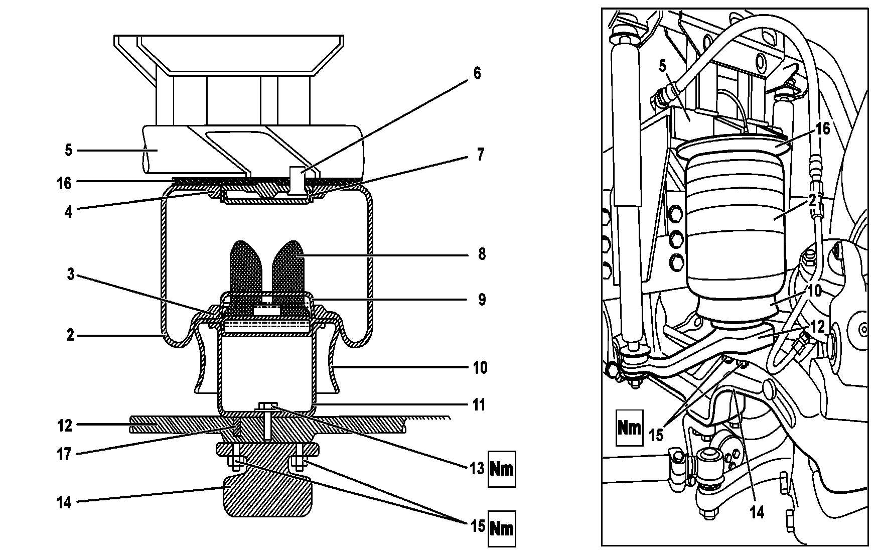
B32.22-0056-09
2 | Pneumatic bellows of the front suspension | 10 | Bellows support and sealing plate | |
3 | Sealing edge of the lower ring on the bracket | 11 | Lower cylindrical bracket | |
4 | Sealing edge of the upper ring on the bracket | 12 | Bracket secured to the front axle | |
5 | Vehicle frame | 13 | Flanged screw fastening the lower cylindrical bracket | |
6 | Threaded nozzle for pneumatic connection | 14 | Front axle | |
7 | Stop pressed onto the support plate | 15 | Self-locking nuts holding the bracket to the axle | |
8 | Bottom sealing edge of the bellows | 16 | Bellows support and sealing plate | |
9 | Sealing edge of the bellows support plate |
| Remove | ||
Danger | Risk of death caused by vehicle slipping or toppling off of the lifting platform. | Align vehicle between vehicle lift columns and position the four support plates at the vehicle lift support points specified by the vehicle manufacturer. | |
1 | Place the vehicle on a suitable lift | When lifting the vehicle by the stringers of the frame and the axle hanging, with the bellows depressurized and without support, the excessive stroke of the dampers may damage them. | |
The most convenient and safe way to work under a vehicle is using a lift with sufficient capacity, so that the mechanic can work standing. | |||
2 | Support the vehicle by the frame on the front and rear | To remove and install the air suspension components of each axle, the vehicle should be safely supported by the structure on four large trestles. In this position, the axles can be easily moved vertically using the lift on which the wheels are supported. | |
3 | Disconnect the negative battery cable or turn off the main switch | For vehicles equipped with electronic engines, always observe the recommendations regarding the care with the vehicle electronics. | |
4 | Remove the wheels | Remove/install wheels | |
Where a suitable lift is used, remove the wheels is not necessary. | |||
5 | Remove the dampers | Remove/install front shock absorber | |
For additional safety and convenience when moving the axle, the dampers can be removed or released from their lower anchors. | |||
6 | Completely depressurize the pneumatic bellows and manually and carefully disengage the front suspension pneumatic bellows (2) from the top sealing edge on the bracket (4) | Do not use metallic tools or levers, this will damage the upper ring sealing edges on the bracket (4) causing subsequent leakage. As a last resort, use a wooden lever with rounded tips. | |
If necessary, move the axle with the lift. | |||
7 | Remove the bellows by pulling it out together with the support plate and bellows seal (10) at the bottom | ||
8 | Disengage the pneumatic bellows (2) from the support plate and bellows sealing (10) | ||
9 | To remove the lower cylindrical bracket, remove from inside the flanged screw (13) screwed to the bracket secured to the front axle (12) | For vehicles 382.189, the bracket (12) secured to the front axle is higher. The lower cylindrical bracket is supported on a disc, in which case the lower cylindrical bracket flanged screw (13) should be removed from outside the bracket. | |
10 | To remove the stop pressed onto the support plate (7), secure the support plate and bellows seal (10) on a vise (with protected jaws) and use an appropriate lever without damaging the sealing edges | If the stop is damaged, it may be cut with a chisel. | |
Releasing the stop by using compressed requires additional safety measures, since the stop may be thrown at a certain distance, causing injury to the operator. | |||
On stops with a central hole, observe the safety measures and apply compressed air until it becomes loose. | |||
11 | If it is necessary to remove the support fixed to the front axle (12), remove the self-locking nuts securing the support to the axle (15) | Remove/install front shock absorber | |
For all vehicles, before removing the bracket attached to the front axle, it is necessary to remove the dampers and bellows. | |||
For vehicle 382 189, the bracket is higher. | |||
| Clean | ||
12 | Clean all mechanical components, the support surfaces and the bellows | The bellows should be dry cleaned without using any cleaning fluid or solvent. | |
Clean the sealing areas on the support plate and the upper edges. | |||
| Check | ||
13 | Check upper ring sealing edges on the bracket (4) and support plate and bellows seal (10) at the bottom | If necessary, replace the support plate or the top bracket. | |
14 | Check the condition of the front suspension pneumatic bellows (2) and the stops pressed on the support plate (7) | Replace pneumatic bellows and stops in case of signs of leaks, dryness, cuts or cracks, deformed internal stops or sealing parts corroded or deformed by prolonged use. | |
| Install | ||
15 | If removed, install on the front axle (14) the bracket fixed to the front axle (12) and new bracket self-locking nuts to the axle (15) | Tighten the new self-locking nuts (15) on the studs screwed on the bracket. | |
In vehicle 382.189, the bracket is higher and features a support disc under the lower cylindrical bracket of the bellows. | |||
Supports of dumpers and bellows on the axle | |||
16 | Install the lower cylindrical bracket (11) on the bracket secured to the front axle (12) and tighten the flanged screw securing the lower cylindrical bracket (13) | For vehicle 382.189, the supporting bracket attached to the front axle is higher, and the flanged screw for securing the lower cylindrical bracket (13) is screwed from outside to the lower cylindrical bracket of the bellows. | |
Bottom fixation of the cylindrical support of the front bellow | |||
Bottom fixation of the cylindrical support of the front bellow | |||
Main support bracket (of the bellow, damper and bars) on the front axle | |||
17 | Press the new stop onto the support plate (7) | Lubricate the stop with the prepared and specified glycerin soap. | |
18 | Slightly lubricate all mechanical sealing parts of the bellows, using the prepared glycerin soap | ||
19 | Manually fit the front suspension bellows (2) on the support plate and bellows seal (10), bending it with the palms of your hands | The bellows should at all times be assembled manually, without using mechanical tools. | |
20 | Install the support plate and bellows seal (10) with the bellows mounted on the lower cylindrical bracket (11), and manually fit the bellows on the upper ring sealing edge on the bracket (4) | The full seating on the top bracket occurs when the bellows are pressurized. | |
21 | Install the dampers if these have been removed | Remove/install front shock absorber | |
22 | Install the wheels if they have been removed | Remove/install wheels | |
Danger | Risk of death caused by vehicle slipping or toppling off of the lifting platform. | Align vehicle between vehicle lift columns and position the four support plates at the vehicle lift support points specified by the vehicle manufacturer. | |
23 | Lower the vehicle from the lift | ||
24 | Connect the negative battery cable or turn on the main switch | For vehicles equipped with electronic engines, always observe the recommendations regarding the care with the vehicle electronics. | |
25 | Run the engine until it achieves the normal operating pressure, and pressurize the pneumatic bellows | ||
26 | Check for potential pressure leaks in the system by using neutral glycerin soap foam or a suitable product for this purpose | Regular soap foam should not be used, since it contains caustic soda, which corrodes the materials. | |
27 | Run a test drive | Check the air suspension behavior. |
Air suspension |
Number | Designation | Model 382.17/180/181/182/184/185/186/187, 634.001/011/012/014 | ||
BA32.22-B-1005-03C | Main support bracket (of the bellow, damper and bars) on the front axle | M12x1.5 10.9 class steel - dumper support | Nm | 100...110 |
M12x1.5 8.8 class steel - stabilizing bar support | Nm | 55 | ||
M14x1.5 | Nm | 140...160 | ||
M16x1.5 | Nm | 230...270 | ||
M18X1.5 | Nm | 330...390 | ||
M20x1.5 | Nm | 460...550 |
Referenced documents
- ar3225b0105g Remove/install front shock absorber
- ar4010b1101a Remove/install wheels
- as0000z001001a Risk of death caused by vehicle slipping or toppling off of the lifting platform.