
W26.10-1202-09
2 | Splitter group shift cylinder | 18 | Shim | 31 | Retaining ring | ||
3 | Splitter group shift rod | 19 | Tapered roller bearing outer race | 32 | Reverse idler shaft | ||
8 | Sliding blocks | 20 | Main shaft | 35 | Screw | ||
9 | Oil pipe | 21 | Synchronizer cone with synchronizer ring and annular spring | 36 | Shift housing | ||
10 | Shift fork for splitter group | 22 | Sliding sleeve | 37 | Front section of transmission housing | ||
11 | Countershaft | 23 | Drive shaft | 38 | Bearing pin | ||
12 | Tapered roller bearing outer race | 25 | Shift | B29 | Countershaft rpm sensor | ||
13 | Shift unit | 26 | Bearing pin | B79 | Transmission oil temperature sensor | ||
14 | Center section of transmission housing | 27 | Tapered roller bearing outer race | S28 | Neutral position switch | ||
15 | Reverse gear | 28 | Tapered roller bearing outer race | S29 | Reverse gear switch | ||
16 | Reverse gear cap | 29 | Countershaft bearing cap | ||||
17 | Range group | 30 | Drive shaft bearing cap |

9 | Oil pipe |
11 | Countershaft |
13 | Shift unit |
14 | Center section of transmission housing |
20 | Main shaft |
50 | Holding device |
W26.50-1239-06

14 | Center section of transmission housing |
33 | 3rd/4th gear shift fork |
38 | Bearing pin |
W26.50-1268-12

20 | Main shaft |
69 | Oil restrictor |
W26.10-1203-06

72 | Transmission |
73 | Assembly device |
W26.10-1204-06
Topical note | Notes on self-locking nuts and bolts | ||
Notes on compressed air connection systems | |||
| Assemble | ||
1 | Assemble countershaft (11) | ||
2 | Assemble drive shaft (23) | ||
3 | Assemble main shaft (20) | ||
4 | Attach assembly device (73) to transmission housing center section (14) and place in upright position | ||
Assembly device | |||
5 | Coat the tread of the tapered roller bearing outer race (19) with lubricant | Grease, silicone-based, 100 g | |
6 | Slide spacer washer (18) onto tapered roller bearing outer race (19) and install using suitable drift from the inside up to the contact surface in the center section of transmission housing (14) | ||
7 | Apply coating of lubricant to contact surface of tapered roller bearing outer race (12) | Grease, silicone-based, 100 g | |
8 | Drive tapered roller bearing outer race (12) into center section of transmission housing (14) from the inside as far as the contact surface using a suitable drift | ||
9 | Install main shaft (20), countershaft (11) and shift unit (13) using holding device (50) into center section of transmission housing (14) |
| |
Transmission 715.528 | |||
Retaining device | |||
Clamping device | |||
10 | Install sliding sleeve (22) | The long collar must point towards the output. | |
11 | Coat tapered roller bearing (pilot bearing) on drive shaft (23) with lubricant and install drive shaft (23) | Push the countershaft (11) to one side. | |
Grease, silicone-based, 100 g | |||
12 | Install both bearing pins (38) | Note the different lengths of the various bearing pins; both bearing pins (38) are longer than the other bearing pins (26). | |
Loctite 5203 sealant | |||
13 | Check bearing and bushing of reverse idler gear (15) for wear and damage | If wear or damage is present: | |
| |||
Replace appropriate component. | |||
14 | Install reverse idler gear (15) with bearing and bush | The long collar of the reverse idler gear (15) must point towards the output. | |
15 | Align reverse idler gear (15) and insert reverse idler shaft (32) | Bolt, reverse idler shaft retaining plate to transmission housing | |
16 | Install radial shaft sealing ring and pilot bushing for splitter group shift rod (3) into transmission housing front section (37) | For this, coat radial shaft sealing ring with lubricant. | |
Synthetic grease 50 g | |||
Drift | |||
17 | Clean sealing surfaces on transmission housing front section (37) and transmission housing center section (14) and coat with sealant | Loctite 5203 sealant | |
18 | Mount transmission housing front section (37) | ||
| Assembly tool for installing shift rod of splitter group | ||
Splitter group shift rod lock to transmission housing | |||
Shift fork bearing pin at transmission housing | |||
Loctite 5203 sealant | |||
Drift | |||
Puller | |||
Retaining device | |||
Alignment punch | |||
19 | Screw in screws/bolts around circumference of transmission housing center section (14) | Pay attention to different lengths of bolts. | |
Bolt, transmission housing front section to transmission housing center section | |||
20 | Coat tread of tapered roller bearing outer races (27, 28) with lubricant | Grease, silicone-based, 100 g | |
21 | Using a suitable drift, install tapered roller bearing outer races (27, 28) up to contact surface | ||
22 | Pull out splitter group shift rod (3) using assembly tool | ||
| Assembly tool for installing shift rod of splitter group | ||
23 | Determine shims of drive shaft (23) and countershaft (11) | ||
| |||
Setting tolerance of bearings on countershaft | |||
Drive shaft bearing pretension | |||
Preload of bushings on drive shaft and countershaft for determining shims | |||
Clamping plates | |||
Pliers | |||
Torque wrench | |||
24 | Install drive shaft bearing cap (30) and countershaft bearing cap (29) with the determined shim | ||
25 | Clean sealing surfaces on center section of transmission housing (14) and reverse idler gear cap (16) and coat with sealant | Loctite 5203 sealant | |
26 | Install reverse idler gear cap (16) | Bolt, reverse idler gear cap to transmission housing center section | |
27 | Detach assembly device (73) from transmission (72) and move transmission (72) to horizontal position | ||
Assembly device | |||
28 | Press in splitter group shift rod (3) using assembly tool | ||
| Assembly tool for installing shift rod of splitter group | ||
29 | Install shift piston of splitter group | ||
30 | Install splitter group shift cylinder (2) | ||
31 | Install shift mechanism (25) | ||
32 | Install transmission oil temperature sensor (B79) |
| |
33 | Install countershaft rpm sensor (B29) | ||
34 | Install reverse gear switch (S29) | ||
35 | Install neutral position switch (S28) | ||
36 | Install oil restrictor (69) into main shaft (20) | ||
37 | Install range group (17) | ||
38 | Install release lever |
| |
39 | Mount bracket of compression air lines and electrical lines at transmission (72) | Screw/bolt, bracket to transmission | |
40 | Connect electrical connectors | ||
41 | Attach compressed-air lines |

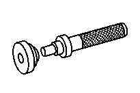


715 589 08 31 00
Assembly device
714 589 05 15 00
Drift
715 589 03 15 00
Alignment punch
315 589 02 31 00
Clamping device


715 589 09 15 00
Drift
000 589 67 21 00
Torque wrench
715 589 01 31 00
Retaining device
715 589 01 37 00
Pliers


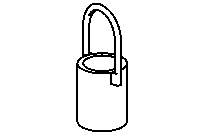
715 589 15 63 00
Clamping plates
715 589 08 33 00
Puller
715 589 05 31 00
Retaining device
Referenced documents
- ah0000n000101a Notes on self-locking nuts and bolts
- ah0018n000101a Notes on compressed air connection systems
- ar2520w0200h Remove and install clutch throwout lever
- ar2610w000101he Attaching and detaching mounting device on transmission
- ar2618w1001hd Remove/install splitter box cylinder
- ar2619w0003hd Remove/install neutral position switch
- ar2619w0010hd Remove/install reverse gear switch
- ar2619w0017hd Remove/install transmission oil temperature sensor
- ar2619w0018hd Remove/install countershaft speed sensor
- ar2631w3100hd Remove/install range group
- ar2635w0001hd Remove/install shift piston of splitter group
- ar2640w247008hd Install front section of transmission housing
- ar2640w247008hd
- ar2650w0004h Remove/install oil restrictor on main shaft
- ar2650w041003hd Determine shims of drive shaft and countershaft
- ar2650w041003hd
- ar2650w0426hd Assembling transmission main shaft
- ar2650w400002hda Install main shaft and countershaft with shift unit
- ar2650w400002hda
- ar2650w400002hdb
- ar2650w400002hdb Install main shaft and countershaft with shift unit
- ar2650w4744hd Dismantle, assemble drive shaft.
- ar2650w4775hd Disassemble, assemble countershaft
- ar2660w0001hd Remove and install gearshift system
- wf5850n263502a Assembly tool for installing shift rod of splitter group