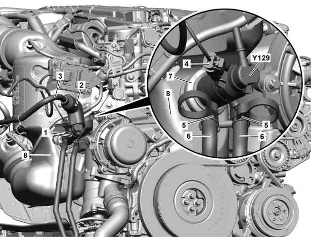
2 | Heat protection insulation |
3 | AdBlue® line |
4 | Electrical connector |
5 | Clip |
6 | Coolant hose |
7 | Clip |
8 | Catalytic converter |
Y129 | AdBlue® metering valve |
P14.40-2653-06
Warning | Risk of burn injuries, suffocation and poisoning when working on the exhaust system and the components connected to it. Risk of suffocation and risk of poisoning caused by inhalation of gaseous and solid components of the exhaust. Risk of poisoning caused by skin contact with solid components of the exhaust. | Wear protective clothing and safety glasses. Use the extraction system. Move people out of the hazard area. | |
Warning | Risk of burn injuries and scalding when working at AdBlue lines and the components attached to them. Risk of injury to skin and eyes when handling AdBlue. Risk of poisoning caused by swallowing AdBlue | Pour AdBlue into suitable containers only. Wait until the pressure is released before starting any work on the exhaust aftertreatment system. | |
Warning | Risk of injury to skin and eyes suffering scalding from contact with hot coolantspray. Risk of poisoning from swallowing coolant. | Do not open cooling system unless coolant temperature is below 90 °C. Open cap slowly and release the pressure. Do not pour coolant into beverage containers. | |
Topical note | Information on preventing damage to electronic components due to electrostatic discharge | ||
Topical note | Notes on avoiding damage through contamination and foreign objects | ||
Topical note | Notes on coolant | ||
Notes on use, material properties and handling of AdBlue® | |||
| Remove/install | ||
1 | Remove upper engine cover. | ||
Installation: Only install upper engine cover after the leak test. | |||
2 | Remove controller unit of NOx sensor from catalytic converter (8). | Engine 654 in model 257 | |
3 | Open heat protection insulation (2). | ||
4 | Release, remove AdBlue® line (3) at AdBlue® metering valve (Y129) and collect escaping AdBlue®. | ||
5 | Clean connection of AdBlue® line (3) with lint-free rag. | ||
6 | Seal openings at AdBlue® line (3) and at AdBlue® metering valve (Y129) with suitable stop plugs. | Record plug | |
7 | Release and disconnect electrical connector (4). | ||
8 | Remove cap from coolant expansion reservoir. |
| |
Engine 654 in model 213, 238 | |||
Installation: Only attach cap after leak test of engine cooling system. | |||
9 | Disconnect coolant hoses (6). | Clamp | |
10 | Remove coolant hoses (6) from AdBlue® metering valve (Y129) and collect escaping coolant. | Installation: Replace clamps (5). | |
Hose clamp pliers | |||
11 | Seal openings at AdBlue® metering valve (Y129) with suitable stop plugs. | Record plug | |
12 | Clean seat of AdBlue® metering valve (Y129) at catalytic converter (8) with clean rag. | ||
13 | Open clamp (7) and remove AdBlue® metering valve (Y129). | Installation: Replace clamp (7) and seal. | |
Bolt, clamp for AdBlue® metering valve to catalytic converter | |||
14 | Seal opening at catalytic converter (8) with protective cover. | Set of protective caps | |
15 | Install in the reverse order. | ||
16 | Check engine cooling system for leak tightness. |
| |
Engine 654 in model 213, 238 | |||
17 | Read out and delete fault memory. | ||
| Engine 654 in model 257 | ||
| Engine 654 in model 238 | ||
| Engine 654 in model 213 | ||
Warning | Risk of accident from vehicle starting off by itself when engine running. Risk of injury (bruises and burns) resulting from working on the engine while it is being started or when it is running. | Secure vehicle to prevent it from starting off by itself. Wear closed and snug-fitting work clothes. Do not touch hot or rotating parts. | |
18 | Carry out engine test run and check engine for proper leak tightness and leak tightness. | ||
19 | Install upper engine cover. |


000 589 54 37 00
Clamp
003 589 03 37 00
Hose clamp pliers
001 589 00 91 00
Set of protective caps
129 589 00 91 00
Record plug
Referenced documents
- ad0000p200004b Connect STAR DIAGNOSIS and read out fault memory
- ad0000p200006fr Connect/disconnect diagnostic unit
- ad0000p200006lwo Connect/disconnect diagnostic unit
- ah0000p500001a Notes on avoiding damage through contamination and foreign objects
- ah1440n000101a Notes on use, material properties and handling of AdBlue®
- ah2000n208001a Notes on coolant
- ah5400p000101a Information on preventing damage to electronic components due to electrostatic discharge
- ar0110p2405olc Remove/install engine cover
- ar1440p2063olc Remove/install NOx sensor with controller unit upstream of catalytic converter
- ar2000p1010oib Inspect cooling system for leaks
- ar2000p1011olc Check engine cooling system for leaktightness
- ar2030p4949oib Remove/install coolant expansion reservoir
- ar2030p4949olc Remove/install coolant expansion reservoir
- as0000z000501a Risk of accident from vehicle starting off by itself when engine running. Risk of injury (bruises and burns) resulting from working on the engine while it is being started or when it is running.
- as1440z000101a Risk of burn injuries and scalding when working at AdBlue lines and the components attached to them. Risk of injury to skin and eyes when handling AdBlue. Risk of poisoning caused by swallowing AdBlue
- as2000z000101a Risk of injury to skin and eyes suffering scalding from contact with hot coolantspray. Risk of poisoning from swallowing coolant.
- as4900z000101a Risk of burn injuries, suffocation and poisoning when working on the exhaust system and the components connected to it. Risk of suffocation and risk of poisoning caused by inhalation of gaseous and solid components of the exhaust.