ENGINE | 651 in MODEL 636, 639 |
ENGINE | 651 in MODEL 900 |
ENGINE | 651.955/956/957 in MODEL 906 |

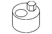
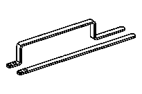

651 589 02 63 00
Assembly tool
651 589 00 40 00
Counterholder
651 589 08 40 00
Counterholder
651 589 01 40 00
Tie-down set

651 589 09 40 00
Holddown device
Use a counterholder for model 900, 906 with code H08 (High-performance A/C) or with code HK4 (Rear A/C), enhanced, for model 636, 639.
Use a counterholder for model 900, 906 without code H08 (High-performance A/C) and without code HK4 (Rear A/C), enhanced, for model 636, 639.
Use hold-down tool up to 31.01.12 or hold-down tool as of 01.02.12.

1 | Install counterholder (6) on screw/bolts of belt pulley (4). |
2 |
Turn engine with counterholder (6) in direction of engine rotation and set to ignition TDC (Top Dead Center). |
The 0° CKA marking on the belt pulley (4) must align with the stay (arrow) on carrier with clamping device (5). |
D03.20-1172-06
3 |
Pull retaining pin (2.1) out from assembly tool (2). |
4 |
Position engine on crankshaft with counter holder (6) to 30° after top dead center. |
The 30° CKA marking on the belt pulley (4) must align with the stay (arrow) on carrier with clamping device (5). |
5 |
Move both halves of assembly tool (2) onto milled surfaces of balance shafts (1). |
6 |
Turn engine on crankshaft with counterholder (6) against direction of engine rotation and set to ignition TDC; guide both halves of assembly tool (2) together and secure with retaining pin (2.1). |
The 0° CKA marking on the belt pulley (4) must align with the stay (arrow) on carrier with clamping device (5). |

7 |
Mark camshaft bearing cap (10). |
Installation: Observe identification of camshaft bearing cap (10). |
8 | Unscrew screw/bolts (9) and remove camshaft bearing caps (10) from camshafts (7). |
9 | Install hold-down tool (8) free of tension on camshafts (7) and tighten. |
10 | Install in the reverse order. |
D05.10-1181-06