AD26.20-W-3003B | Electronic power shift (EPS) diagnosis operational check without tester on display | 7.11.97 |
TRANSMISSION 710.4 /5 /7, 717.2 /3 /5 /6 /7, 719.5 /8 in MODEL 625.1 /2, 655, 656, 657, 658, 659
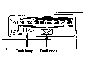
W26.20-0022-01
| The function check permits a limitation of the fault possibilities and should, as a basic principle, be carried out before operations on the EPS system. Faults are shown by the illumination of the display (1) and code numbers (2) in the display. | ||
| The connection of secondary electric consumers to the existing EPS fuses may, in the event of short-circuit or overloading, leave the EPS inoperative. | ||
Electronic power shift (EPS), diagnosis previous knowledge | |||
EPS diagnostic tools | |||
| On-Board voltage 24 V (Specific density 1.16, with undervoltage fault code 17). | ||
| Indicator lamp for secondary consumers must be out. | ||
| Compressed air at least 5.5 bar. | ||
Function check | |||
Test step / scope of test | Operation / requirement | Specified value | Possible cause / remedy |
1 Display function | Ignition: ON | All figures / symbols illuminate approx. 4 s. | Fuse F11 defective |
2 Warning buzzer function and D+ actuation | Ignition: ON Start engine | Charge indicator lamp goes out | |
3 Shift processes | Ignition: ON Actuate clutch pedal Shift through gears N, 1-8, R. Reverse gear with function knob. Actuate splitter switch. | All gears (N, 1-8, R, splitter) are displayed according to actuation. | Actuate transmission tooth on tooth (actuate clutch pedal again if necessary / briefly start engine and repeat test step). Check compressed air supply and test step 4. |
4 Check whether fault code no. apperas in the display – The fault codes no. 1-18 show stored electrical faults – Faults occurring intermittently (loose contact) are also only displayed intermittently during driving. – The fault lamp lights up in conjunction with fault codes no. 1-18 | Ignition: ON Note illuminating code nos. as these may be erased after the following programming. Carry out programming in the following sequence: 1. Switch off all electric consumers. 2. Switch off ignition (for at least 15 s). 3. Actuate clutch pedal and hold. 4. Hold shift lever in neutral position. 5. Switch on ignition. The programming process lasts approx. 15 seconds. | The following codes may appear in the display during programming: 1a Fault codes 21-26 appear in display only during programming. 1b Previously displayed (noted) fault codes no. 1-18 do not appear in display during programming. | Fault is constantly present. In the sequence: 1. Remove all previously displayed fault codes 1-18 and then carry out programming. 2. Check electrical and pneumatic connections on transmission for correct connection. 3. Mechanical defect in transmission. |
The fault code no. is shown again in the display after switching off engine and switching on ignition again. Fault codes no. 21-26 show deviations from the sensor specified travel values during programming. | – When installing a new control unit, part no. 006 545 6632 or 006 545 6732, only 8 and N are displayed when programming. – The driver or customer should also be informed about the programming process. – Re-program in the event of undervoltage or jump-starting. With undervoltage programming should take place with jump-starting batteries. | 2. New fault codes no. 21-26 appear in display. Fault codes no. 1-18 do not appear in display. | In the sequence: 1. Check electrical and pneumatic connections on transmission for correct connection. 2. Sensor outside travel tolerance (replace on trial), refer to (fault code assignment table). 3. Mechanical defect in transmission |
3. If programming has not taken place: Previously displayed (noted) fault codes no. 1-18 re-appear in display. Moving off and stopping in 4th gear or higher with rubbing clutch also shows fault code 7 in display. | Fault is constantly present. Carry out test steps in accordance with fault code no. displayed: | ||
4. Previously displayed (noted) fault codes no. 1-18 no longer appear in display. N. Neutral position is shifted/displayed following programming. | Fault is currently not present. Check components and plug connections appropriate to displayed fault code no. for correct functioning / loose contact: | ||
5. Before and after programming no display in display, yet complaint on transmission. | 1. Check electrical and pneumatic connections on transmission for correct connection. 2. Mechanical defect in transmission. 3. Possibly change control electronics on trial. |
Referenced documents
- ad2620w200101a EPS diagnosis tools
- ad2620w200115b EPS assignment of fault codes during programming
- ad2620w2001b Electronic power shift (EPS) diagnosis basic knowledge
- ad2620w600120a EPS test of electrical system D+ actuation charge indicator lamp control unit
- ad2620w600121b EPS test of electrical system readout in display
- ad2620w600122a EPS test of electrical system actuation of fault lamp
- ad2620w600123b EPS test of electrical system actuation of display
- ad2620w600124b EPS test of electrical system warning buzzer
- ad2620w6001b Electronic power shift (EPS) test of electrical system