AR46.20-T-3015CA | Check and adjust center steering position on steering gear | 28.5.02 |
MODEL NMB613.364 /365 /367 /368
with ZF steering 8098 for O560

T46.20-0045-06
Markings on steering gear
1 Universal joint
6 Primary shaft

T46.40-0022-01
2 Steering shaft
3 Steering gear pitman arm

T46.20-0032-12
Markings on miter gear

T46.20-0031-01
Miter gear
4 Clamping bolt
5 Universal joint of steering shaft
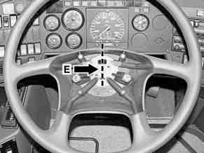
T46.20-0033-01
Markings on steering wheel
Danger! | Risk of injury caused by moving parts that can pinch, crush or, in extreme cases even sever extremities. | No parts of the body or limbs should be within the operating range of the mechanism when components are in motion. | |
| Notes on self-locking nuts and bolts | All models | |
1 | Lift/jack up vehicle | ||
2 | Move steering to center position | If steering is set to the center position the steering gear pitman arm (3) and steering idler arm are set parallel to the vehicle's longitudinal axis. | |
3 | Check position of markings (arrows) on steering gear pitman arm (3) relative to steering shaft (2) | Markings (arrows) on the steering gear pitman arm (3) and steering shaft (2) must line up. | |
If necessary, correct the position of the markings (arrows) by turning the steering gear pitman arm (3). | |||
| |||
| |||
| |||
4 | Remove cover above steering gear | ||
5 | Clean steering gear in area of marking (A) | Depending on the model and version three notches may be present on the steering gear in the area of the marking (A). In this event the center notch must be used as the marking (A). | |
6 | Check that marking (A) on steering gear and marking (C) on primary shaft (6) line up, adjust if necessary | If necessary, turn the steering wheel until marking (A) and marking (C) line up. | |
In the following work steps, in which further markings are to be tested, the alignment of marking (A) to marking (C) must be maintained. | |||
7 | Check alignment of markings (arrows D) on miter gear, adjust if necessary | If necessary: Remove steering gear side universal joint from miter gear. Turn steering wheel until the markings (arrows D) line up. Then mount steering gear side universal joint onto miter gear. | |
| |||
| |||
8 | Check steering shaft universal joint (5) on miter gear is in correct position, adjust if necessary | The lower gap of the clamping piece must point forwards and the clamping bolt (4) must be transverse to the direction of travel. | |
If necessary: Remove steering shaft universal joint (5) from miter gear. By turning the steering wheel correct the position of the steering shaft universal joint (5). Then mount the steering shaft universal joint (5) onto the miter gear. | |||
| |||
| |||
9 | Check alignment of marking (E) of steering wheel and steering shaft, adjust if necessary | If necessary, remove the steering wheel from the steering shaft and correct by shifting the position. | |
| |||
| |||
10 | Check front axle alignment | Only perform if the steering gear pitman arm (3) was removed from the steering shaft (2) and then mounted again. |
Steering wheel, jacket tube, steering shaft
Number | Designation | Model | |
BA46.10-N-1002-05G | Nut, steering wheel to steering shaft | Nm | 68 |
Steering gear
Number | Designation | Model | |
BA46.20-N-1004-01F | Nut, pitman arm to steering shaft | Nm | 575 |
BA46.20-N-1008-01F | Bolt with self-locking nut, universal joint to steering repeater gear and steering shaft | Nm | 50 |
Tie rod
Number | Designation | Model | |
BA46.40-N-1002-01F | Castellated nut, tie rod to steering knuckle arm | Nm | 265 |


001 589 67 21 00
Torque wrench
Torque wrench
000 589 39 21 00
Henviste dokumenter
- ah0000n000101a Oplysninger om selvlåsende bolte og møtrikker
- ar0060t1000b
- ar4020t0100c
- as0000z000901a Fare for personskade som følge af klemning af legemsdele, i værste fald fare forafskæring af legemsdele ved indgreb i mekanikken