
P33.10-2224-09
1 Front axle carrier
1f Screw
1g Screw
1i Vehicle jack support point
2 Connector
3 Retaining plate
10a Tie rod joint
17 Spring control arm
25f Locking plate
30f Return flow pipe
30h Sealing ring
30i High pressure expansion hose
30k Return line mounting clamp
80a Lower steering shaft
a Drift (diameter: 14.8 mm)
Y10 SPS [PML] solenoid valve
17a Hexagon bolt
18 Torque strut
18a Hexagon bolt
23 Rack-and-pinion steering
23a Screw
23g Screw
25 Steering coupling
25a Screw
Modification notes
28.2.07 | Bolt, steering coupling to steering shaft | Model 220.083/084/087/183/184/187 | |
21.3.07 | Bolt, steering coupling to steering shaft | Model 220.083/084/087/183/184/187 |
| Remove/install | ||
| Notes on self-locking nuts and bolts | ||
1 | Remove the front wheels | ||
| Remove/install wheels | ||
2 | Suction off oil from expansion reservoir of power steering | Hand pump | |
3 | Remove return line (30f) at return hose | Collect oil which runs out with rags and seal line connections with plugs. | |
| |||
4 | Remove fastening clamp (30k) for return line at longitudinal member | ||
5 | Unscrew high-pressure expansion hose (30i) | Collect oil which runs out with rags and seal line connections with plugs. | |
| |||
Installation: Check sealing ring (30h) for damage, replace if necessary. | |||
| |||
| |||
| |||
| |||
6.1 | Deactivate easy entry/exit function | Vehicles with memory package (driver seat, steering column, mirrors) code 275 | |
Otherwise the driver seat and steering wheel move into a different position if the driver door is opened or closed for example. Damage to the upper frame can occur when the holding device is installed. | |||
It is switched off using the buttons on the steering wheel in the "Comfort" menu on the multifunction display, see vehicle owner's manual. | |||
7 | Move front wheels to straight-ahead position and secure steering wheel. | To do this, swivel the sun visor to one side and insert the retainer. | |
The steering wheel must not be turned when the steering coupling has been removed. This will damage the fanfare horns and airbag clock spring contact beyond repair. | |||
| |||
8 | Remove torsion bar on front axle | Do not disconnect the link rod from the stabilizer bar. | |
MODEL 220 except 220.083 /084 /087 /183 /184 /187, except Active Body Control (ABC) code 487 | |||
MODEL 220.083/ 084/ 087/ 183/ 184/ 187 | |||
9 | Disconnect plug (2) from SPS solenoid valve (Y10) | ||
10 | Unscrew bolt (25a) of steering coupling (25) at lower steering shaft (80a) | Replace locking plate (25f) with self-locking nut. | |
| |||
11 | Insert suitable tool into the hole in the steering coupling (25) and pull the lower steering shaft (80a) upwards out of the steering coupling (25) | Do not counter by holding the rubber boot or the temperature-resistant plastic disk on the lower steering shaft (80a). Do not use force (hammer blows, a lot of leverage), if necessary expand clamping groove slightly using a screwdriver. | |
Installation: When inserting, pay attention to the pin for the steering coupling (25) and groove of the lower steering shaft (80a) (arrows). | |||
12 | Press tie rod joints (10a) out of steering knuckles | MODEL 220 except 220.083 /084 /087 /183 /184 /187 | |
MODEL 220.083/ 084/ 087/ 183/ 184/ 187 | |||
13 | Put on engine carrier arm | ||
14 | Detach both engine mounts from front axle carrier (1) by removing bolts (1g) | Installation: The anti-twist locks in the front axle carrier (1) must latch into the retaining grooves of the engine mount. | |
| |||
15 | Raise engine at front lifting eye | Ensure that rear of the engine does not touch the body. | |
16 | Remove torque struts (18) from front axle carrier (1) and fold forwards | The hexagon bolt (18a) must not turn. When loosening the nut always counterhold the hexagon bolt (18a), otherwise the lock tabs for caster adjustment in the rubber bushing will be sheared off. | |
Installation: Do not tighten the nut of the hexagon bolt (18a) until the vehicle is in the ready-to-drive condition. The rubber mount in the torque strut (18) must not be installed distorted. | |||
Model 220 except 220.08/18 | |||
Model 220.08/18 | |||
17 | Remove spring control arm (17) from front axle carrier (1) and fold backwards | The hexagon bolt (17a) must not be twisted. When loosening the nut always counterhold the hexagon bolt (17a), otherwise the lock tabs for camber adjustment in the rubber bushing will be sheared off. | |
Installation: Do not tighten the nut of the hexagon bolt (17a) until the vehicle is in the ready-to-drive condition. The rubber mount in the spring control arm (17) must not be installed distorted. | |||
Model 220 except 220.08/18 | |||
Model 220.08/18 | |||
18 | Remove rubber plugs for centering bores (front axle carrier (1) to longitudinal member) | ||
19 | Support front subframe (1) | Use assembly attachment | |
Transmission plate for passenger cars and commercial vehicles | |||
20 | Remove bolts (1f) on front axle carrier (1) | The bolts (1f) are self-tapping, so the following points must be observed: Never recut the thread in the longitudinal member Replace bolts Use only original bolts (4 x) Do not attach bolts at an angle Do not use an impact bolt tightener Observe tightening torque | |
Installation: Before tightening the bolts (1f), align the front axle carrier (1) on the left and right using drift (a, 14.8 mm diameter). | |||
| |||
21 | Remove heat shields from front axle carrier (1) | ||
22 | Lower front axle carrier (1) | Ensure that the high-pressure expansion hose (30i) and the return line (30f) for the steering are not damaged. | |
23 | Remove bolts (23a, 23g), remove rack-and-pinion steering (23) and retaining plate (3) from the front axle carrier (1) | ||
24 | Remove sheet metal nuts for attaching the engine compartment cover | ||
25 | Remove jack tube (1i) from front axle carrier (1) | ||
26 | Install in the reverse order | ||
27 | Fill power steering pump and bleed | MODEL 220 except 220.028 /074 /128 /163 /174 /176 /179 | |
MODEL 220.028 /128, except Active Body Control (ABC) code 487 | |||
MODEL 220.028 /063 /065 /070 /073 /074 /075 /128 /165 /170 /173 /174 /175 /176 /178 /179, 230.467 /474 /475 /476 /479 with Active Body Control (ABC) code 487 | |||
28 | Check steering for function and leaks | There is a grease cushion under the cover cap. A slight escape of grease is to be regarded as normal and should not be confused with leakage. | |
29 | Perform wheel alignment check | ||
Model 215, 220 except 220.875/878 and except 220.175/178 with CODE (979) Special protection version with code (Z07) Maximum protection | |||
Model 220.175/178 with CODE (979) Special protection version with code (Z07) Maximum protection | |||
Model 220.875/878 |
Power steering pump
Number | Designation | Model | ||
BA46.30-P-1003-01C | High-pressure expansion hose to power steering pump | M141.5 | Nm | - |
M161.5 | Nm | 40 | ||
Power steering pump
Number | Designation | Model | Model | ||
BA46.30-P-1003-01C | High-pressure expansion hose to power steering pump | M141.5 | Nm | - | - |
M161.5 | Nm | 40 | - | ||
BA46.30-P-1020-01C | Union nut, high-pressure line to power steering pump | Nm | - | 40 | |
Power steering pump
Number | Designation | Model | Model | ||
BA46.30-P-1003-01C | High-pressure expansion hose to power steering pump | M141.5 | Nm | - | - |
M161.5 | Nm | 40 | 40 | ||
BA46.30-P-1012-01C | Banjo bolt, high pressure expansion hose (Active Body Control) to power steering pump | Nm | - | 45 | |
Power steering pump
Number | Designation | Model | Model 220.083/084/087/183/184/187 | ||
BA46.30-P-1003-01C | High-pressure expansion hose to power steering pump | M141.5 | Nm | - | - |
M161.5 | Nm | 40 | - | ||
BA46.30-P-1012-01C | Banjo bolt, high pressure expansion hose (Active Body Control) to power steering pump | Nm | 45 | - | |
BA46.30-P-1016-01C | Banjo bolt, high pressure expansion hose to power steering pump | Nm | - | 45 | |
Power steering pump
Number | Designation | Model | ||
BA46.30-P-1003-01C | High-pressure expansion hose to power steering pump | M141.5 | Nm | - |
M161.5 | Nm | 40 | ||
BA46.30-P-1012-01C | Banjo bolt, high pressure expansion hose (Active Body Control) to power steering pump | Nm | 45 | |
Steering shaft
Number | Designation | Model | Model 220.083/084/087/ | ||
BA46.10-P-1001-01E | Bolt, steering coupling to steering shaft | Stage 1 | Nm | 30 | 20 |
Stage 2 | ° | - | - | ||
Engine mount, engine support (engine side)
Wheel control, hub
Number | Designation | Model | Model | Model 220.08/18 | Model 220.875/ | ||
BA33.20-P-1001-01F | Self-locking nut, spring control arm to front axle carrier | Stage 1 | Nm | 210 | 80 | - | 210 |
Stage 2 | ° | - | 120 | - | - | ||
BA33.20-P-1002-01F | Self-locking nut, torque strut to front axle carrier | Stage 1 | Nm | 210 | 80 | - | 210 |
Stage 2 | ° | - | 120 | - | - | ||
BA33.20-P-1008-01F | Self-locking nut, lower wishbone to front axle carrier | Nm | - | - | 110 | - | |
Front axle carrier

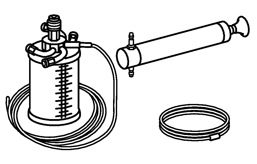


129 589 01 21 00
Thrust piece
Holding device
Hand pump
Puller
210 589 00 71 00
140 589 00 63 00
124 589 03 33 00

Set of stop plugs
129 589 00 91 00
Henviste dokumenter
- ah0000n000101a Oplysninger om selvlåsende bolte og møtrikker
- ap4010p4050z Af-, påmontering og om nødvendigt omplacering af hjul
- ar0110p750003i
- ar3220p0300i
- ar3220p0300iw
- ar3310p010003i
- ar4020p0200i
- ar4020p0200i
- ar4020p0200mb
- ar4020p0200mb
- ar4020p0200mp
- ar4630p0010b
- ar4630p0010i
- ar4630p0010n Påfyldning og udluftning af servopumpe
- ar4640p020002i Udtrykning af samt montering af sporstangsled fra akselspindel
- ar4640p020002iw Sporstangsled trykkes ud af akselspindel, monteres