ar3220d0200h

Remove/install front spring

Type ar · emne 32.20 · version 0313 · 2020-06-25

Gælder for: Model 900, 906

Ikke tilgængelig på “da”; vises på Engelsk.

Placering

Funktionsgruppe 2 Chassis › 32 Affjedring › 32.20 Stålaffjedring, torsionsstang, niveaumat — Serie 900 · Serie 906

EinPAS 20 Undervogn › 20.16 affjedring › 20.16.30 fjeder/fjederbælg/støddæmper/fjederben — Serie 900 · Serie 906

AR32.20-D-0200H

Remove/install front spring

24.06.2020

Model

900, 906

Remove/install front spring

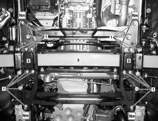
1

Bolts

2

Spring clamp plates

3

Front axle spring

D32.20-1112-06

Remove/install front spring

D32.20-1123-01

D32.20-1122-01

D33.20-1124-01

7

Torsion bar linkage

8

Stop plate

9

Reinforcement plate

10

Transverse control arm

11

Articulated rod

Warning

Risk of injury caused by pinching or crushing when working on springs or spring bodies that are under tension

Use only approved tensioning devices; additionally screen off hazardous area if necessary. Check special tools for damage and proper operation (visual inspection). Wear protective gloves.

AS00.00-Z-0001-01A

Topical note

Notes on self-locking nuts and bolts

AH00.00-N-0001-01A

Notes on repair work on suspension components

AH00.00-P-0100-01A

Remove/install

1

Secure vehicle on vehicle lift

AR00.60-D-0100H

2

Loosen screws/bolts (1) and unscrew gradually by approx. 10 mm


Unscrew the screws/bolts (1) gradually by approx. 10 mm because the spring clamp plates (2) are under spring load.
Otherwise the threads can get damaged.

Screw, lower spring clamp plate to front axle carrier

*BA32.20-N-1001-01A

3

Unscrew screws/bolts (1) and remove spring clamp plates (2)

Installation: Screw in the screws/bolts (1) leaving approx. 10 mm thread length exposed.

4

Detach left and right torsion bar linkage (7) from stabilizer bar

Nut, stabilizer bar linkage to stabilizer bar

*BA32.35-N-1002-02G

5

Detach left and right stop plate (8) from transverse control arm (10)

Bolt, stop plate to transverse control arm/bump stop

*BA33.20-N-1002-01N

6

Detach ball head of articulated rod (11) of front axle headlamp range adjustment level sensor from transverse control arm (10)

Model 900, 906
with code LG0 (Bi-xenon headlamps)
Model 900, 906
with code LG1 (Bi-xenon headlamps with cornering function)

7

Detach left drive shaft from output flange of front axle transmission


Model 906
with code ZG1 (Engageable all-wheel drive)
Model 906
with code ZG3 (Engageable all-wheel drive with gear reduction)

AR33.30-D-0100-01H


Detach the left drive shaft from the output flange of the front axle transmission.
Otherwise the output flange will be pulled out of the transfer case and the shaft seal will be damaged.

Loctite 262

*BR00.45-Z-1059-02A

Model 906
with code ZG1 (Engageable all-wheel drive)
Model 906
with code ZG3 (Engageable all-wheel drive with gear reduction)Bolt, input shaft to front axle gear

*BA33.30-N-1001-07A

8

Loosen left transverse control arm (10) at front axle and pry out

AR33.20-D-1452H

9

Remove reinforcement plate (9)

Model 906
with code ZG1 (Engageable all-wheel drive)
Model 906
with code ZG3 (Engageable all-wheel drive with gear reduction)

Bolt, reinforcement plate to front axle carrier

*BA33.10-N-1007-01C

10

Remove front axle spring (3)

Helper required.

11

Check spring bearing for wear and damage

In event of wear or damage

Install a new spring bearing.

12

Install in the reverse order

Front-axle steel suspension

Number

Designation

Model 900

Model 906

BA32.20-N-1001-01A

Screw, lower spring clamp plate to front axle carrier

M8

Nm

29

29

M10

Nm

-

-

M12x1.5

Stage 1

Nm

106

106

Stage 2

°

90

90

Front axle stabilizer bar

Number

Designation

Model 900

Model 906

BA32.35-N-1002-02G

Nut, stabilizer bar linkage to stabilizer bar

M12

Nm

106

106

Front axle carrier

Number

Designation

Model 906

BA33.10-N-1007-01C

Bolt, reinforcement plate to front axle carrier

M8

Nm

29

Wheel control, hub

Number

Designation

Model 900

Model 906.11/13/21/23/61/63/71/73

BA33.20-N-1002-01N

Bolt, stop plate to transverse control arm/bump stop

M10

Nm

58

58

M12x1.5

Stage 1

Nm

106

106

Stage 2

°

90

90

Wheel control, hub

Number

Designation

Model 906.15/25/65

BA33.20-N-1002-01N

Bolt, stop plate to transverse control arm/bump stop

M10

Nm

58

M12x1.5

Stage 1

Nm

106

Stage 2

°

90

Drive shaft

Number

Designation

MODEL 906 with CODE ZG1, ZG2, ZG3, ZG4

BA33.30-N-1001-07A

Bolt, input shaft to front axle gear

Nm

58

Repair materials

Number

Designation

Order number

BR00.45-Z-1059-02A

Loctite 262

Henkel AG & Co. KGaA
http://www.loctite.de

Henviste dokumenter