
G25.40-3154-09
1 | Compressed-air line | 10 | Drain screw | 20 | Hydraulic line | ||
2 | Drive shaft | 11 | Hydraulic line | 21 | Connector | ||
3 | Electrical connectors | 12 | Timing case | 22 | Bracket | ||
4 | Clip | 13 | Bolt | 23 | Left support arm | ||
5 | Flexible exhaust pipe | 14 | Bolt | X66 | WSK oil level sensor connector | ||
6 | Hydraulic line | 15 | Engine mount | Y11 | WSK decoupler | ||
7 | Hydraulic line | 16 | Eyelet | Y12 | Torque converter lockup clutch | ||
8 | Hydraulic hose | 17 | Bolt | ||||
9 | Oil filter housing | 18 | Torque converter clutch |

19 | Torque converter |
G25.40-3149-01
Danger ! | Risk of death. There is a risk of death to persons located within the tilting range or underneath the raised dump body during operation. Risk of injury There is a risk of body parts being crushed or pinched when the dump body is lowered. | All persons must remain outside the tilting range of the dump body during its operation. Always secure the raised dump body with the dump body support before starting any work underneath it. | |
Danger ! | Risk of injury to skin or eyes from hydraulic fluid spraying out under pressure.Risk of poisoning from swallowing hydraulic fluid. | Depressurize hydraulic system completely before starting any work on it. Wear protective clothing and safety glasses. | |
| Notes on self-locking nuts and bolts | ||
| Remove/install | ||
1.1 | Raise and secure dump platform | Engine 900, 904 | |
See operator's manual. | |||
1.2 | Remove tipper platform | engine 902, 906 | |
See operator's manual. | |||
Bolt, tilt cylinder to platform | |||
2 | Detach flatbed auxiliary frame | engine 902, 906 | |
Installation: Replace nuts. | |||
3 | Tilt cab |
| |
4 | Remove compressed-air line (1) | Installation: Check compressed air line (1) for leaktightness. | |
5 | Remove drive shaft (2) from output flange of torque converter clutch (18), place upwards and strap down | Screw/bolt, drive shaft to torque converter clutch output flange | |
6 | Detach electrical connections (3) | ||
7 | Release clamp (4) and remove flexible exhaust pipe (5) from valve fitting | Installation: Clean sealing surfaces, check clamp (4) for wear and replace if necessary. | |
8 | Remove both hydraulic lines (6, 7) and collect escaping oil | With work hydraulics | |
9 | Seal open connection fittings using suitable stop plugs | ||
10 | Work loose hydraulic hose (8) at oil filter housing (9) | With work hydraulics | |
so that air is drawn in. | |||
11 | Drain oil of torque converter clutch (18) and collect oil | ||
| |||
12 | Disconnect WSK oil level sensor connector (X66) | ||
13 | Remove hydraulic line (11) and collect escaping oil | ||
14 | Seal open connection fittings using suitable stop plugs | ||
15 | Remove hydraulic line (20) with connector (21) and collect escaping oil | engine 902, 906 | |
Installation: Clean sealing surfaces and replace seal of connector (21). | |||
Screw/bolt, hydraulic line connector to oil pan | |||
16 | Seal open connection fittings using suitable stop plugs | ||
17 | Detach both brackets (22) from timing case (12) | engine 902, 906 | |
18 | Install cranking device (12) at timing case | ||
Inspection hole cap to timing case | |||
Turning device | |||
19 | Remove all 6 bolts (13) from clutch plate | Crank engine by the crankshaft in the normal direction of rotation until the bolts (13) are visible. | |
Screw/bolt, torque converter to drive plate | |||
20 | Remove bolts (14) of engine mounts (15) on left and right | Installation: Insert bushing beforehand. | |
Screw/bolt, engine support to engine mount | |||
21 | Detach left support arm (23) from torque converter clutch (18) | engine 902, 906 | |
Screw/bolt, engine support to torque converter clutch housing | |||
22 | Lift engine slightly and secure on timing case (12) using jack stand | ||
23 | Hook in lifting equipment on the eyelet (16) on the torque converter clutch (18) and on overhead crane or boom crane | ||
24 | Remove bolts (17) from timing case (12) | Screw/bolt, torque converter clutch to timing case | |
25 | Remove torque converter clutch (18) | Remove some of the cable ties on the cable harnesses above the left and right engine mounts (15). | |
Installation: Apply coating of long-life grease to hub (arrow) of torque converter (19). | |||
Long-life grease | |||
26 | Remove drive plates of torque converter clutch (18). | ||
27 | Install in the reverse order | ||
| Check | ||
28 | Check oil level of torque converter clutch (18) | ||
| |||
29 | Perform a test drive and check function | ||
30 | Check torque converter clutch (18) for leaktightness | Visual inspection. |
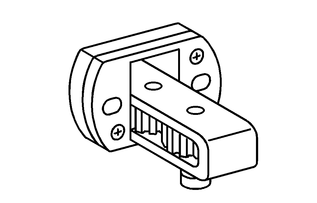
904 589 04 63 00
Turning device
Henviste dokumenter
- ah0000n000101a Oplysninger om selvlåsende bolte og møtrikker
- ap2540g2502b Momentomformer - olie- og filterskift
- ap2540g2510b Kontrol, korrektion af momentomformerens oliestand
- ar0330g160003b
- ar2540g1400bb
- ar6080g0005b
- ar6080g0005b
- as0000z001301a Fare for kvæstelser på hud og øjne på grund af sprøjtende hydraulikvæske, som erunder højt tryk. Forgiftningsfare ved indtagelse af hydralikvæske
- as5520z000101a Livsfare under brug af tippelad ved ophold i tippeområdet eller under den hævedetipbro. Fare for personskade på grund af fastklemning og knusning af legemsdele,når tipbroen sættes af