AR15.30-W-7100C | Remove/install starter | 15.2.12 |
ENGINES 457.9 in MODEL 374, 375, 940, 942, 943, 944, 958
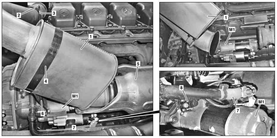
W15.30-1030-09
Shown on model 944
1 Muffler
2 Clip
3 Lifting eye
4 Tensioning strap
8 Electric cable circuit 50
M1 Starter
5 Heat shield
6 Bracket
7 Terminal 30 cables
Modification notes
| Remove/install | ||
1 | Switch off ignition | ||
Danger! | Risk of injury caused by body parts being pinched or crushed as cab is tilted | Ensure that no one is within the tilting range of the cab as it is being tilted. Always tilt the cab all the way to the end position and secure with the safety strut. | |
2 | Tilt cab | ||
| Notes on tilting the cab | ||
Danger! | Risk of explosion caused by escaping oxyhydrogen gas. Risk of injury caused by caustic burns to eyes, skin and mucous membranes from battery electrolyte (contains diluted sulfuric acid) or metal spatter due to short circuit. Risk of burn injuries caused by short circuit. Risk of poisoning caused by swallowing battery electrolyte (contains diluted sulfuric acid) or absorption of lead over the skin or orifices | No fire, sparks, open flames or smoking. Wear acid-resistant gloves and clothing and safety glasses with side guards. Do not place any conductive objects on the battery and avoid any short circuit from battery positive to ground. Only fill liquid battery electrolyte (diluted sulfuric acid) into suitable and appropriately marked containers. | |
3 | Disconnect ground lead from battery | ||
| Notes on battery | ||
4 | Remove soundproofing on frame above on the right | ||
5 | Remove heat shield (5) on turbocharger and engine brake flap fitting | | |
6 | Remove tensioning strap (4) on muffler (1) and bracket (6) | Installation: Inspect tensioning strap (4), install new one if necessary. | |
7 | Remove clamp (2) on rear lifting eye (3) | Installation: Inspect clamp (2), install new one if necessary. | |
8 | Remove muffler on engine brake flap fitting (1), push away to the rear and bind up | Clean sealing surfaces. | |
Installation: Check clamp, replace if necessary. | |||
9 | Disconnect electrical lines of circuit 30 (7) at starter (M1) | | |
10 | Remove cable tie and disconnect electrical line for circuit 50 (8) on starter (M1) | Installation: Install new cable ties. | |
| |||
11 | Remove starter (M1) and bracket (6) | Take out starter (M1) upwards. | |
| |||
12 | Inspect starter pinion for wear | In case of wear, replace the starter (M1). | |
13 | Inspect ring gear of flywheel for wear | If worn: | |
Replace ring gear of flywheel | |||
14 | Install in the reverse order | ||
15 | Synchronize time between tachograph disk and display |
Turbocharger
Number | Designation | Engine | ||
BA09.40-N-1005-01M | Bolt, heat shield to turbocharger and engine brake flap fitting | Nm | 20 | |
Starter
Henviste dokumenter
- ah5410p000101a Oplysninger om batterier
- ah5410p000101a
- ah6080n000301a Oplysninger om tipning af førerhus
- ar0330w8312c
- as5410z000101a Brand-/eksplosionsfare på grund af kortslutning og udsivende knaldgas. Forbrændingsfare/fare for personskade ved ætsning af øjne, hud og sliminder på grund af batterielektrolyt/-tåge, kortslutning og lysbuepåvirkning. Fare for
- as6080z000101a Fare for personskade ved fastklemning og knusning, når førerhuset tippes