Modification notes |
20.07.2020 | Special tool 124 589 24 21 00 (pressure pump) added. | Operation step 37 | |
20.07.2020 | Method modified. | Operation steps 36, 40, 41, 42, 43, 44, 45 | AR08.50-S-0017-01F |
20.07.2020 | Special tool 124 589 24 21 00 (pressure pump) added. | Operation steps 40, 41, 43, 44 | AR08.50-S-0017-01F |
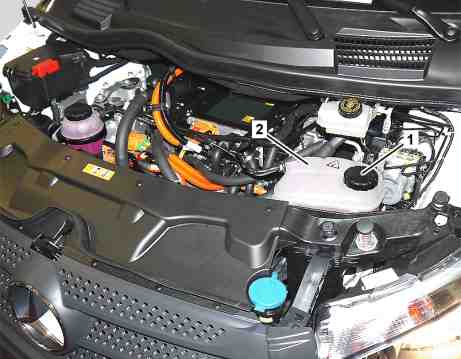
1 | Cap |
2 | Coolant expansion reservoir |
S20.00-A015-81
S20.00-A016-79
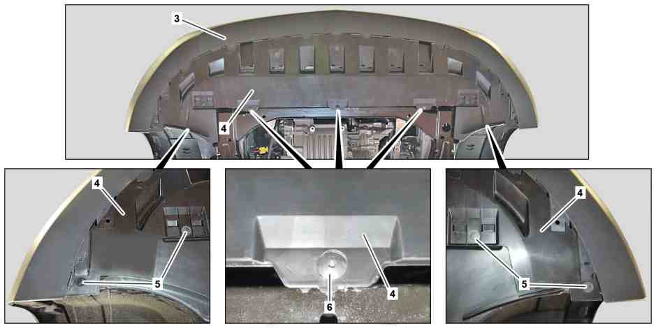
3 | Bumper | 5 | Expansion rivet | 6 | Screw | ||
4 | Trim |
S20.00-A017-78
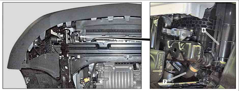
7 | Coolant hose line | 8 | Cooler |

S20.00-A018-78
9 | Coolant hose | 11 | Coolant hose line | 12 | Switchover valve | ||
10 | Coolant line |

S08.50-A013-78
12 | Switchover valve | 14 | Clamp | 15 | Coolant hose | ||
13 | Coolant line |

2 | Coolant expansion reservoir |
16 | Tester cap |
17 | Pressure pump |
S08.50-A012-81
Danger | Risk of death when working on component parts and systems with U >= 30 V alternating voltage (AC) or U >= 60 V direct voltage (DC) | Do not touch damaged or defective live component parts and lines or non-insulated electrical connections and lines. | |
Warning | Risk of injury to skin and eyes suffering scalding from contact with hot coolantspray. Risk of poisoning from swallowing coolant. | Do not open cooling system unless coolant temperature is below 90 °C. Open cap slowly and release the pressure. Do not pour coolant into beverage containers. | |
Topical note | General information on vehicles with high-voltage on-board electrical system and/or lithium-ion battery and/or gaseous-fuel drive system as well as personal protective equipment | ||
Topical note | Notes on avoiding damage through contamination and foreign objects | ||
Topical note | Notes on coolant | ||
Topical note | Notes on battery | ||
Notes on coolant level for high-voltage battery cooling system | |||
Drain off | |||
1 | Set operating unit of the climate control to position "0." | | |
2 | Lock electric coolant pumps using vehicle diagnosis system. | ||
| Connect STAR DIAGNOSIS and read out fault memory | ||
Work through specified procedure completely. | |||
Do not yet remove vehicle diagnosis system. | |||
3 | Remove cap (1) of coolant expansion reservoir (2). | First, twist open cap (1) of coolant expansion reservoir (2) counterclockwise to the safety catch and release overpressure, then remove cap (1). | |
4 | Raise vehicle. | ||
5 | Remove expansion rivets (5). | ||
6 | Remove screws (6). | ||
7 | Remove trim (4) from the integral carrier and from the bumper (3). | Pay attention to catch hooks and guides between the bumper (3) and trim (4). | |
8 | Remove coolant hose line (7) from cooler (8) and drain coolant. | ||
Collect coolant. | |||
Commercially available devices/tools | |||
9 | Lower vehicle. | ||
10 | Attach tester cap (16) to coolant expansion reservoir (2). | Test cap | |
11 | Attach pressure pump (17) to tester cap (16). | Pressure pump | |
Test cap | |||
12 | Use pressure pump (17) to generate pressure until coolant no longer escapes. | | |
Collect coolant. | |||
Commercially available devices/tools | |||
Pressure pump | |||
13 | Raise vehicle. | ||
14 | Reattach coolant hose line (7) to cooler (8). | ||
15 | Attach trim (4) to the integral carrier and to the bumper (3). | If no additional work is required in this area. | |
Pay attention to catch hooks and guides between the bumper (3) and trim (4). | |||
16 | Tighten screws (6). | If no additional work is required in this area. | |
17 | Install expansion rivets (5). | If no additional work is required in this area. | |
Check expansion rivet (5) for damage. | |||
If damage is present, | |||
| |||
Replace damaged expansion rivets (5). | |||
18 | Remove coolant hose line (11) from the switchover valve (12) and drain coolant. | ||
Collect coolant. | |||
Commercially available devices/tools | |||
19 | Lower vehicle. | ||
20 | Use pressure pump (17) to generate pressure until coolant no longer escapes. | | |
Collect coolant. | |||
Commercially available devices/tools | |||
Pressure pump | |||
21 | Raise vehicle. | ||
22 | Reattach coolant hose line (11) to the switchover valve (12). | ||
23 | Remove coolant hose (9) from the coolant line (10) and drain coolant. | Collect coolant. | |
Commercially available devices/tools | |||
Hose clamp pliers | |||
24 | Lower vehicle. | ||
25 | Use pressure pump (17) to generate pressure until coolant no longer escapes. | | |
Collect coolant. | |||
Commercially available devices/tools | |||
Pressure pump | |||
26 | Raise vehicle. | ||
27 | Reattach coolant hose (9) to coolant line (10). | Check clamp for damage. | |
Hose clamp pliers | |||
If damage is present, | |||
| |||
Replace clamp. | |||
28 | Remove coolant hose (15) from the coolant line (13) and drain coolant. | Collect coolant. | |
Commercially available devices/tools | |||
Hose clamp pliers | |||
29 | Lower vehicle. | ||
30 | Use pressure pump (17) to generate pressure until coolant no longer escapes. | | |
Collect coolant. | |||
Commercially available devices/tools | |||
Pressure pump | |||
31 | Raise vehicle. | ||
32 | Reattach coolant hose (15) to coolant line (13). | Check clamp for damage. | |
Hose clamp pliers | |||
If damage is present, | |||
| |||
Replace clamp. | |||
33 | Lower vehicle. | ||
34 | Remove pressure pump (17). | Pressure pump | |
Pour in | |||
35 | Put the high-voltage on-board electrical system into operation. | If the high-voltage on-board electrical system is not in operation. | |
36 | Attach charger to 12 volt on-board electrical system battery. | ||
The filling and bleeding of the coolant circuit with the diagnostic system takes some time; for this purpose, a constant 12 volt power supply is required. | |||
37 | Pour coolant into the coolant circuit of the high-voltage battery. | ||
| |||
Evacuate coolant circuit, check, and fill. | |||
Electric drive cooling system | |||
Test cap | |||
Cooler vacuum filling device | |||
NTKL Adaption | |||
Electric vacuum pump | |||
Pressure pump | |||
38 | Bleed coolant circuit for high-voltage battery using diagnostic system. | ||
| Connect STAR DIAGNOSIS and read out fault memory | ||
The coolant pumps are released automatically when they are bled. | |||
The duration of the bleeding process of the cooling circuit of the high-voltage battery is approx. 30 min. | |||
39 | Remove charger from 12 volt on-board electrical system battery. | ||
| Check | ||
40 | Check coolant level of the coolant circuit of the high-voltage battery. | If necessary: | |
| |||
Correct coolant level. | |||
Electric drive cooling system | |||
41 | Check coolant circuit of the high-voltage battery for leak tightness. |
Cooling system |
Number | Designation | Engine 780.701/702 in model 447 | |||
BF08.50-N-1001-01F | Electric drive cooling system | Cooling system of high-voltage battery and vehicle interior | Filling capacity | Liter | 10 |
Cooling system of electric motor | Filling capacity | Liter | 5 | ||
For both cooling systems, entire filling capacity, in the workshop | Filling capacity | Liter | 15 | ||
Antifreeze/water | Down to -37 °C | % | 50/50 | ||
Coolant specifications | |||||
Sheet | |||||


285 589 01 21 00
NTKL Adaption
454 589 00 37 00
Hose clamp pliers
210 589 00 91 00
Test cap
124 589 24 21 00
Pressure pump


285 589 02 21 00
Electric vacuum pump
285 589 00 21 00
Cooler vacuum filling device
Henviste dokumenter
- ad0000s200004e
- ah0000p500001a Oplysninger om forebyggelse af skader på grund af snavs og fremmedlegemer
- ah0000z030001a Generelle oplysninger ved køretøjer med højvoltsnet og/eller litium-ion-batteri og/eller gasdrivsystem samt personligt beskyttelsesudstyr
- ah0850s005101f Oplysninger kølervæskestand for højvoltsbatterikølesystem
- ah2000n208001a Oplysninger om kølervæske
- ah5410p000101a
- ah5410p000101a Oplysninger om batterier
- ar0060s1000e
- ar0850s0011f
- ar0850s001701f
- ar2020p744101rq
- ar4770s1000f
- ar5410s1127e
- as0000z003501a Livsfare ved arbejde på komponenter og systemer med U >= 30 V vekselspænding (AC) eller U >= 60 V jævnspænding (DC)
- as2000z000101a Risiko for skoldningsskader på hud og øjne pga. sprøjtende, varm kølervæske. Risiko for forgiftning ved indtagelse af kølervæske