
D07.02-1115-09
Shown on engine 642.896/898 |
1 | High pressure pump | 6 | High-pressure fitting | 11 | Sealing ring | ||
2 | Fuel hose | 7 | Electrical connector | 12 | Gear | ||
3 | Fuel hose | 8 | Screw | 15 | Fuel temperature sensor | ||
4 | Electrical connector | 9 | Coolant hose | 16 | Quantity control valve | ||
5 | Pressure line | 10 | Bracket (engine 642.896/898) |

Variant I |
12 | Gear |
13 | Groove |
13a | Left edge |
A | Tooth |
E | Tooth |
F | Tooth |
D07.02-1123-11

Variant II |
12 | Gear |
13 | Groove |
13a | Left edge |
A | Tooth |
E | Tooth |
F | Tooth |
D07.02-1124-11
Caution | Risk of injury to skin and eyes due to handling of engine oil. Risk of poisoning caused by swallowing engine oil | Wear protective gloves, protective clothing and safety glasses. | |
Danger | Risk of explosion caused by fuel igniting, risk of poisoning caused by inhaling and swallowing fuel as well as risk of injury to eyes and skin caused by contactwith fuel. | No fires, sparks, open flames or smoking. Pour fuels into suitable and appropriately marked containers only. | |
Topical note | Notes on self-locking nuts and bolts | ||
Topical note | Notes on self-locking nuts and bolts | ||
Notes about Common-Rail components | |||
| Remove | ||
1 | Remove fan shroud |
| |
Engine 642.896/898/992/993 in model 906 | |||
2 | Remove coolant hose (9) from bracket (10) and press toward the rear | Engine 642.896/898 in model 906 | |
3 | Disconnect electrical connector (7) from quantity control valve (16) | To do this, expose electric line. | |
4 | Remove electrical connector (4) from fuel temperature sensor (15) | ||
5 | Remove fuel hoses (2, 3) from high-pressure pump (1) | | |
Collect escaping fuel. | |||
Pliers for click clamps | |||
Record plug | |||
6 | Remove pressure line (5) from high-pressure fitting (6) and press upward slightly | | |
| |||
Collect escaping fuel. | |||
Record plug | |||
7 | Remove high-pressure fitting (6) | If the high-pressure fitting (6) is loose or leaky. | |
8 | Set piston of cylinder 1 at the crankshaft to ignition TDC | | |
Observe marking on belt pulley. | |||
Socket wrench bit | |||
9 | Remove screws/bolts (8) | ||
10 | Remove high-pressure pump (1) | ||
11 | Remove gear (12) for high-pressure pump (1) | If installing a new high-pressure pump (1). | |
| Clean | ||
12 | Clean sealing surfaces of the high-pressure pump (1) | Cold degreasing agent/cold cleaning solvent HAKU 1025-920 | |
| Install | ||
13 | Fix gear (12) for high-pressure pump | If a new high-pressure pump (1) has been installed. | |
14 | Install new sealing ring (11) | Coat sealing ring (11) with engine oil. | |
15 | Attach marking to tooth (A) of the gearwheel (12) | For this purpose, the high-pressure pump (1) must be stopped in the removed state in the installation position on the cylinder head. | |
Place groove (13) vertically, determine tooth (A) from the left edge (13a) of the groove (13) vertically upward and mark. | |||
16 | Attach markings to teeth (E, F) of the gearwheel (12) | For this purpose, the high-pressure pump (1) must be stopped in the removed state in the installation position on the cylinder head. | |
Starting from tooth (A) and proceeding counterclockwise, determine teeth (E, F). Here, tooth (A) is the 1st tooth, tooth (E) is the 5th tooth, and tooth F is the 6th tooth. | |||
17 | Adjust gearwheel (12) relative to high-pressure pump (1) | For this purpose, the high-pressure pump (1) must be stopped in the removed state in the installation position on the cylinder head. | |
Teeth (E, F) must be positioned in the center at the top. | |||
18 | Attach high-pressure pump (1) to cylinder head | | |
19 | Screw in new screws (8) | ||
Topical note | Notes on self-locking nuts and bolts | ||
Bolt, high-pressure pump to cylinder head | |||
20 | Screw high-pressure fitting (6) into high-pressure pump (1) | If loose or leaky high-pressure fitting (6) has been removed. | |
Replace sealing ring. | |||
High-pressure fitting to high-pressure pump | |||
| Check | ||
21 | Check clamps and fuel hoses (2, 3) | If there is damage. | |
| |||
Replace damaged clamps and/or fuel hoses (2, 3). | |||
22 | Check sealing cone of the pressure line (5) | If there is damage. | |
| |||
Install new pressure line (5). | |||
23 | Attach pressure line (5) to high-pressure fitting (6) | ||
Topical note | Notes on threaded connections fastened using a tightening angle-based tightening process | ||
Note on calculation of tightening torque when using insertion or socket tools with various effective lengths | |||
| |||
Ensure correct seating of pressure line (5). | |||
Pressure line to high-pressure pump | |||
Box wrench bit | |||
24 | Attach fuel hoses (2, 3) to high-pressure pump (1) | Pliers for click clamps | |
25 | Connect electrical connector (4) to fuel temperature sensor (15) | ||
26 | Connect electrical connector (7) to quantity control valve (16) | ||
27 | Attach coolant hose (9) to bracket (10) | Engine 642.896/898 in model 906 | |
28 | Install fan shroud |
| |
Engine 642.896/898/992/993 in model 906 | |||
29 | Switch on ignition before engine start | If a new high-pressure pump (1) has been installed. | |
| |||
Because of this, the new high-pressure pump (1) is filled with fuel. | |||
| Check | ||
Danger | Risk of explosion caused by fuel igniting. Risk of injury to skin and eyes caused by fuel spraying out at high pressure | Keep all ignition sources out of hazard area. | |
Warning | Risk of accident from vehicle starting off by itself when engine running. Risk of injury (bruises and burns) resulting from working on the engine while it is being started or when it is running. | Secure vehicle to prevent it from starting off by itself. Wear closed and snug-fitting work clothes. Do not touch hot or rotating parts. | |
30 | Check for leak tightness with engine running | Visual inspection only. |

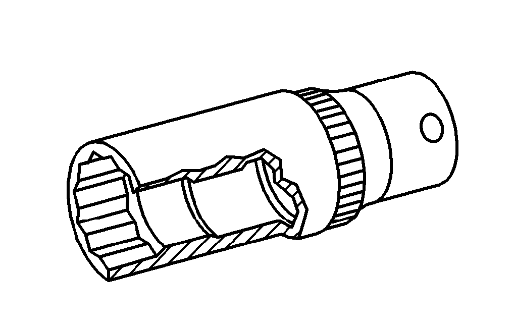


000 589 69 03 00
Box wrench bit
001 589 65 09 00
Socket wrench bit
129 589 00 91 00
Record plug
171 589 00 37 00
Pliers for click clamps
Henviste dokumenter
- ah0000n000101a Oplysninger om selvlåsende bolte og møtrikker
- ah0000p001501cw Oplysning om beregning af tilspændingsmoment ved anvendelse af indstiksværktøj eller påsætningsværktøj af forskellig længde
- ah0000p002001a Oplysninger om skrueforbindelser, som er fremstillet efter den drejevinkelstyrede tilspændingsmetode
- ah0716p000201tx Oplysninger om common rail-komponenter
- ar0702d1021sf
- ar2040d6800m
- ar2040d6800sf
- as0000z000501a Fare for ulykke ved automatisk igangsætning når motoren kører. Fare for personskade på grund af knusning og forbrænding, hvis der arbejdes mens motoren startes eller kører
- as0716z000101a Fare for eksplosion på grund af antændelse af brændstof. Fare for personskade påhud og øjne på grund af udstrømmende brændstofstråle
- as1800z000101a Fare for personskade på hud og øjne ved håndtering af motorolie. Fare for forgiftning ved indtagelse af motorolie
- as4700z000101a Fare for eksplosion ved tænding, fare for forgiftning ved indånding og indtagelse af brændstof samt fare for hud- og øjenskader ved kontakt med brændstof