
1 | Wiring harness |
2 | Bracket |
3 | Heat shield |
Y635 | Camshaft adjuster solenoid |
W05.00-1065-12

W05.00-1066-09
4 | Bracket (for code B3H (Secondary water retarder)) | 7 | Intake rocker arm assembly | B601 | Camshaft position sensor | ||
5 | Coolant pipe (for code B3H (Secondary water retarder)) | 8 | Exhaust rocker arm assembly | ||||
6 | Clamps | 9 | Bracket |

W05.00-1071-08
7 | Intake rocker arm assembly | 10 | Screw/bolts | 13 | Camshaft | ||
8 | Exhaust rocker arm assembly | 11 | Rocker arm housing |

11 | Rocker arm housing |
12 | Camshaft bearing halves |
14 | Seal |
Pfeil | Range |
W05.00-1068-05

11 | Rocker arm housing |
15 | Rocker arm assembly |
16 | Pin |
Pfeile | Hole |
W05.00-1074-05
Danger ! | Risk of accident from vehicle starting off by itself when engine running. Risk of injury (bruises and burns) resulting from working on the engine while it is being started or when it is running. | Secure vehicle to prevent it from starting off by itself. Wear closed and snug-fitting work clothes. Do not touch hot or rotating parts. | |
Danger ! | Risk of injury caused by body parts being pinched or crushed as cab is tilted | Ensure that no one is within the tilting range of the cab as it is being tilted. Always tilt the cab all the way to the end position and secure with the safety strut. | |
| Notes on avoiding damage through contamination and foreign objects | ||
| Notes on tilting the cab | ||
| Remove | ||
1 | Tilt cab | ||
2 | Remove soundproofing | ||
3 | Drain coolant at engine radiator | ||
4 | Remove compressor resonator | ||
5 | Disconnect electrical connection from camshaft adjuster solenoid (Y635) | ||
6 | Expose wiring harness (1) on rocker arm housing (11) | ||
7 | Remove camshaft adjuster solenoid (Y635) | Turn camshaft adjuster solenoid (Y635) clockwise and pull out. | |
8 | Remove bracket (2) | ||
9 | Remove bracket (4) for coolant pipe (5) | Only on vehicles with code B3H (Secondary Water Retarder). | |
10 | Remove heat shield (3) | ||
11 | Remove exhaust gas recirculation cooler | ||
12 | Remove bracket (9) | ||
13 | Remove cylinder head cover | ||
14 | Remove injectors wiring harness | ||
15 | Attach turning device for engine | ||
Bolt, turning device to flywheel housing | |||
Turning device | |||
16 | Place engine at ignition TDC on cylinder 1 and lock | ||
Turning device | |||
Drift | |||
Template | |||
17 | Remove screw/bolts (10) for inlet rocker arm assembly (7), the exhaust rocker arm assembly (8) and the rocker arm housing (11) | ||
Observe loosening procedure for rocker arm housing (11). | |||
18 | Remove bearing cap for inlet rocker arm assembly (7) and the exhaust rocker arm assembly (8) | Mark installation position of bearing cap. | |
19 | Remove intake rocker arm assembly (7) and exhaust rocker arm assembly (8) | ||
20 | Remove rocker arm housing (11) from cylinder head | Note the camshaft bearing halves (12) in the rocker arm housing (11). | |
21 | Remove camshafts (13) | ||
The camshafts (13) must be removed to check the camshaft bearing halves (12) in the cylinder head. | |||
22 | Check camshaft bearing halves (12) for wear and damage | Check camshaft bearing halves (12) for wear, score marks or scratches. | |
23 | Check camshafts (13) for wear and damage | Check contact surfaces for camshafts (13) for wear, score marks or scratches. | |
| Install | ||
24 | Clean sealing surfaces on the cylinder head and rocker arm housing (11) | ||
25 | Insert new seal (14) on rocker arm housing (11) | Fasten seal (14) in the area (arrow) of the camshaft adjuster solenoids (Y635) with sealant in order to avoid falling out of the seal (14) during installation of the rocker arm housing (11). | |
26 | Place rocker arm housing (11) on cylinder head | Check whether seal (14) is seated correctly. | |
27 | Insert inlet rocker arm assembly (7) and exhaust rocker arm assembly (8) in the rocker arm housing (11) | The drifts (16) on the rocker arm assemblies (15) must sit in the bores (arrows) of the rocker arm housing (11). | |
28 | Insert bearing cap for inlet rocker arm assembly (7) and the exhaust rocker arm assembly (8) | Note the applied markings during removal. | |
29 | Insert screw/bolts (10) for rocker arm housing (11) and tighten down | ||
Observe tightening procedure for rocker arm housing (11). | |||
Bolt, spring steel sheet for solenoid on camshaft positioner to rocker arm frame | |||
Bolt, bracket for rocker arm assembly to cylinder head | |||
Screw/bolt, rocker arm frame to cylinder head | |||
30 | Install bracket (9) | Bracket, exhaust gas recirculation cooler clamps to cylinder head | |
31 | Install exhaust gas recirculation cooler | ||
Check clamps (6) for exhaust gas recirculation cooler for damage; replace if necessary. | |||
32 | Install heat shield (3) | ||
33 | Install bracket (4) for coolant pipe (5) | Only on vehicles with code B3H (Secondary Water Retarder). | |
Bolt, retarder coolant pipe bracket on retarder coolant pipe | |||
Bolt, bracket for retarder coolant pipe to rocker arm frame | |||
34 | Install bracket (2) | Coolant line bracket to rocker arm frame | |
35 | Install camshaft adjuster solenoid (Y635) | ||
36 | Fasten wiring harness (1) to rocker arm housing (11) | ||
37 | Connect electrical connection to camshaft adjuster solenoid (Y635) | ||
38 | Remove turning device at flywheel housing | ||
Bolt, TDC inspection hole cap to flywheel housing | |||
Turning device | |||
39 | Remove drift from flywheel housing | Drift | |
40 | Install crankshaft position sensor and tighten down screw/bolt | Replace sealing ring. | |
Bolt, crankshaft position sensor to flywheel housing | |||
41 | Remove template on rocker arm housing (11) | Template | |
42 | Install injectors wiring harness | ||
43 | Install cylinder head cover | ||
44 | Install compressor resonator | ||
45 | Pour in coolant | ||
46 | Perform an engine test run, stop engine and check in the area of the cylinder head cover and the rocker arm housing (11) for leaktightness | Visual inspection. | |
47 | Install soundproofing | ||
48 | Tilt back cab |
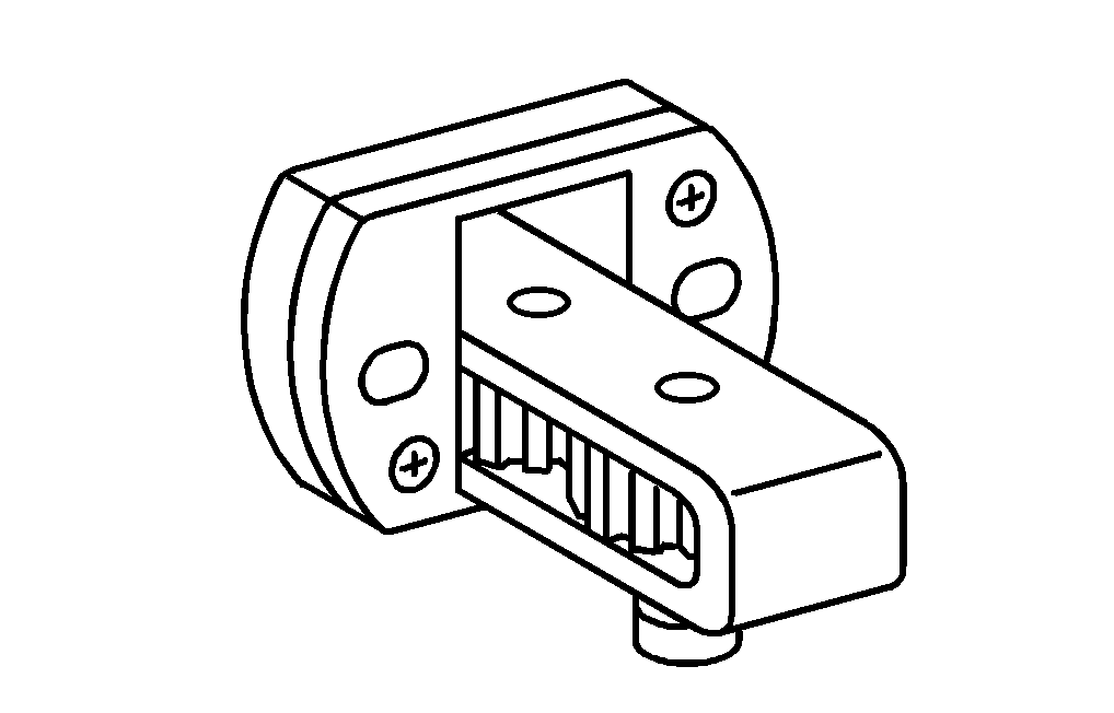


904 589 04 63 00
Turning device
936 589 00 15 00
Drift
936 589 00 23 00
Template
Henviste dokumenter
- ah0000n500001h Oplysninger om forebyggelse af skader på grund af snavs og fremmedlegemer
- ah6080n000301a Oplysninger om tipning af førerhus
- ar0120w5014md
- ar0330w160003md
- ar0500w555101md
- ar0500w555102md
- ar0510w762003md
- ar0520w6992md
- ar0716w1008md
- ar0716w1008md
- ar1310w5840md
- ar1420w7665md
- ar2000w1142m
- as0000z000501a Fare for ulykke ved automatisk igangsætning når motoren kører. Fare for personskade på grund af knusning og forbrænding, hvis der arbejdes mens motoren startes eller kører
- as6080z000101a Fare for personskade ved fastklemning og knusning, når førerhuset tippes