
Shown on engine 642.992 |
1 | Cylinder head cover |
2 | Engine charge air duct |
3 | Screw |
4 | Bracket |
5 | Screw |
6 | Steering hydraulic fluid container |
7 | Screw |
8 | Coolant pipe (engine 642.992/993) |
9 | Screw/bolt (engine 642.992/993) |
10 | Rail |
D01.20-1024-06

Shown on engine 642.992 |
1 | Cylinder head cover |
11 | Screw |
12 | Fuel line |
13 | Injection line |
14 | Fuel hose |
15 | Fuel hose |
16 | Fuel filter |
17 | Screw |
18 | Engine wiring harness |
19 | High pressure pump |
32 | Leak oil line |
D01.20-1039-06

Shown on engine 642.896 |
7 | Screw |
12 | Fuel line |
22 | Bracket |
25 | Bracket (engine 642.896/898) |
26 | Coolant hose (engine 642.896/898) |
27 | Coolant hose (engine 642.896/898) |
28 | Bracket (engine 642.896/898) |
29 | Bracket (engine 642.896/898) |
30 | Vacuum line |
31 | Brake booster |
32 | Leak oil line |
33 | Retainer (engine 642.896/898/993) |
34 | Glow output stage |
D01.20-1038-06
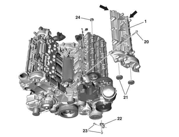
1 | Cylinder head cover |
20 | Screw |
21 | Cover |
22 | Bracket |
23 | Bolts |
24 | Cover |
D01.20-1025-06
Danger | Risk of explosion caused by fuel igniting, risk of poisoning caused by inhaling and swallowing fuel as well as risk of injury to eyes and skin caused by contactwith fuel. | No fires, sparks, open flames or smoking. Pour fuels into suitable and appropriately marked containers only. | |
| Remove/install | ||
1 | Drain off coolant |
| |
2 | Detach vacuum line (30) on brake booster (31) and place to one side | Installation: Check seal on brake booster (31) for damage, replace if necessary. | |
3 | Remove cover of left cylinder head cover (1) | ||
4.1 | Remove screw/bolt (7) and push bracket (25) with coolant hose (26) towards the front | Engine 642.896/898 in model 906 | |
4.2 | Remove screw/bolts (7, 9) and push coolant pipe (8) to one side | Engine 642.992/993 in model 906 | |
Bolt, coolant pipe to housing for coolant thermostat | |||
5 | Unscrew screws/bolts (3, 5) and remove bracket (4) | ||
6 | Remove rail (10) on left cylinder head | ||
7 | Remove engine charge air duct (2) and hang up to the side | Bolt, charge air line upstream of charge air cooler to bracket | |
8 | Remove steering hydraulic fluid container (6) and hang up to the side | Bolt, power steering oil reservoir to cylinder head cover and oil filter | |
9 | Remove injector on left cylinder head | ||
10 | Remove bracket (29) with glow output stage (34) and lay down to the side | Engine 642.896/898 in model 906 | |
Unclip coolant hose (27) from bracket (28). Do not disconnect electrical connections from glow output stage (34). | |||
Bolt, bracket to charge-air distributor | |||
11 | Remove injection line (13) from cylinder head cover (1) and high-pressure pump (19) | Installation: Check sealing cone of injection line (13) for damage; replace if necessary. | |
Pressure line to high-pressure pump | |||
Bolt, retaining clamp of high-pressure line to cylinder head cover | |||
12.1 | Pull retainer (33) and disconnect leak oil line (32) from fuel line (12) | Engine 642.896/898/993 in model 906 | |
Seal leak oil line (32) and fuel line (12) using suitable stop plugs. | |||
Installation: Check sealing rings for damage, and replace leak oil line (32) if necessary. | |||
Record plug | |||
12.2 | Open clamp and remove leak oil line (32) from fuel line (12) | Engine 642.992 in model 906 | |
Seal leak oil line (32) and fuel line (12) using suitable stop plugs. | |||
Installation: Check clamp for damage, replace if necessary. | |||
Record plug | |||
13 | Remove fuel hose (14) at high-pressure pump (19). | Seal openings with suitable stop plug. | |
Installation: Check clamp for damage, replace if necessary. | |||
Record plug | |||
14 | Remove fuel hoses (15) from fuel filter (16) | Seal off fuel hose (15) with suitable stop plugs. | |
Installation: Check clamp for damage, replace if necessary. | |||
Record plug | |||
15 | Remove engine wiring harness (18) at cylinder head cover (1) and expose | Installation: Check retaining clips for engine wiring harness (18) for damage; replace if necessary. | |
16 | Remove screw/bolts (11, 17) and swivel fuel line (12) to one side | ||
17 | Unscrew screws/bolts (23) and remove bracket (22) | Bolt, holder to oil filter housing and cylinder head cover | |
18 | Loosen and remove screw/bolts (20) in stages and in reverse order of the tightening procedure, for a cooled engine | Bolt tightening procedure for cylinder head cover | |
Installation: | |||
Screw/bolt, cylinder head cover to cylinder head | |||
19 | Press off cylinder head cover (1) to the corners (arrows) carefully from the cylinder head using a suitable tool | ||
Notes on sealant path for cylinder head cover | |||
| |||
The cylinder head cover (1) can only be replaced in combination with the cylinder head. | |||
Installation: Replace cover (21, 24). | |||
Sealant, Loctite 5970, 50 ml | |||
Application gun | |||
If cylinder head cover (1) is damaged | |||
| |||
Replace cylinder head cover (1) and cylinder head. | |||
20 | Install in the reverse order | ||
Warning | Risk of accident from vehicle starting off by itself when engine running. Risk of injury (bruises and burns) resulting from working on the engine while it is being started or when it is running. | Secure vehicle to prevent it from starting off by itself. Wear closed and snug-fitting work clothes. Do not touch hot or rotating parts. | |
21 | Conduct engine test run and check engine for leaktightness in the area of the cylinder head cover (1) |


112 589 00 25 00
Application gun
129 589 00 91 00
Record plug
Henviste dokumenter
- ah0130n100008se Oplysninger om tætningsmiddelforløb ventildæksel
- ar0120d501403sf
- ar0120d5015sg
- ar0130d5770sf
- ar0703d1010sf
- ar0716d1000sf
- ar2000d1140sd
- as0000z000501a Fare for ulykke ved automatisk igangsætning når motoren kører. Fare for personskade på grund af knusning og forbrænding, hvis der arbejdes mens motoren startes eller kører
- as4700z000101a Fare for eksplosion ved tænding, fare for forgiftning ved indånding og indtagelse af brændstof samt fare for hud- og øjenskader ved kontakt med brændstof