
W01.10-1050-09
Shown on engine 926.9 |
1 | Engine mount | 7 | Compressed-air line | 12 | Fuel line (return flow) | ||
2 | Engine wiring harness | 8 | Suction line (steering) | 13 | Oil filling line | ||
3 | Clip | 9 | Pressure line (steering) | 14 | Electrical wiring harness (only for vehicles with code H03 (air conditioning in the front-end assembly)) | ||
4 | Exhaust pipe | 10 | Power steering pump | 15 | A/C compressor (only for vehicles with code H03 (air conditioning in the front-end assembly)) | ||
5 | Manual transmission | 11 | Fuel line (feed) | 16 | Coolant pipe | ||
6 | Clutch booster (only for attached clutch booster on the manual transmission) |

W01.10-1051-08
Shown on vehicle with manual transmission |
17 | Electrical connection1) | 22 | Ground cable | M1 | Starter | ||
18 | Air intake pipe | 23 | Electrical line, terminal 30 | X29 | Transmission connector | ||
19 | Air intake hose | 24 | Bracket | XM.31 | Motor ground point | ||
20 | Compressed-air line | B132 | SCR air temperature and air humidity combination sensor1) | 1) | Only on vehicles with code MS4 (BlueTec 4) or with code MS5 (BlueTec 5) | ||
21 | Engine brake cylinder |

Vehicles with code MS4 (BlueTec 4) or with code MS5 (BlueTec 5) |
25 | Coolant line |
26 | AdBlue feed line |
27 | Compressed-air line |
28 | Metering device |
29 | Coolant line |
Y107 | SCR tank heater solenoid valve |
W01.10-1052-05
| Remove/install | ||
Warning | Risk of injury to skin and eyes suffering scalding from contact with hot coolantspray. Risk of poisoning from swallowing coolant. | Do not open cooling system unless coolant temperature is below 90 °C. Open cap slowly and release the pressure. Do not pour coolant into beverage containers. | |
Topical note | Notes on self-locking nuts and bolts | ||
1 | Disconnect electrical engine wiring harness (2) from the cab-chassis connector |
| |
Warning | Risk of injury caused by body parts being pinched or crushed as cab is tilted | Ensure that no one is within the tilting range of the cab as it is being tilted. Always tilt the cab all the way to the end position and secure it with the safety strut. | |
2 | Tilt cab | ||
Topical note | Notes on tilting the cab | ||
3 | Remove noise encapsulation from the top left and right frame | ||
4 | Expose electrical engine wiring harness (2) and connect to the engine | ||
5 | Open cap on fuel tank | ||
6 | Remove hydraulic-pneumatic power shift (HPS) lines from the engine and tie to one side | ||
Only for vehicles with code GS3 (Gearshift, "hydraulic"). | |||
7 | Remove radiator |
| |
Engine 902 with code BA1 (Voith retarder, performance optimized), engine 926 | |||
8 | Remove coolant pipes from engine to retarder | ||
Only for vehicles with code BA1 (performance optimized Voith retarder) or with code BA9 (Voith secondary retarder R 115). | |||
9 | Remove coolant pipes from engine to automatic transmission | Only on vehicles with automatic transmissions. | |
10 | Remove coolant hose from the coolant pump and remove with the coolant pipe (16) | Installation: Check clamps; replace if necessary. | |
11 | Slacken poly-V-belt and remove | ||
Only on vehicles with code H03 (Air conditioning in front end). | |||
12 | Expose electrical wiring harness (14) and disconnect electrical connector from the A/C compressor (15) | Only on vehicles with code H03 (Air conditioning in front end). | |
13 | Remove A/C compressor (15) from the engine and fasten to the frame | Only on vehicles with code H03 (Air conditioning in front end). | |
Screw/bolt, A/C compressor to carrier | |||
14.1 | Remove power-steering pump (10) from the compressor and fasten to the frame | If the engine continues to be used. | |
Do not disconnect the suction line (8) and pressure line (9). | |||
Installation: Align drive of the power-steering pump (10) to the cross plate of the compressor. | |||
Bolt, power steering pump to compressor | |||
14.2 | Disconnect suction line (8) and pressure line (9) of the steering | When installing a new engine. | |
Capture hydraulic oil. | |||
Oil pressure line to power steering pump | |||
Oil suction line to power steering pump | |||
Connection fitting to power steering pump | |||
15 | Remove cross plate from the power steering pump (10) or from the compressor | Only if the engine continues to be used. | |
Installation: Secure cross plate against sliding with long-life grease. | |||
Long-life grease | |||
16 | Remove oil filling line (13) from the oil pan and tie to one side | Plug openings. | |
Installation: Check sealing ring and clamp of the oil filling line (13); replace if necessary. | |||
Danger | Risk of explosion caused by fuel igniting, risk of poisoning caused by inhaling and swallowing fuel as well as risk of injury to eyes and skin caused by contactwith fuel. | No fires, sparks, open flames or smoking. Pour fuels into suitable and appropriately marked containers only. | |
17 | Disconnect fuel lines (11, 12) from the main fuel filter | Mark installation position of the fuel lines (11, 12). Collect escaping fuel and close off bores. | |
Installation: Check O-rings and replace if necessary. Observe marking of fuel lines (11, 12). | |||
Nut, feed line and return line to fuel filter | |||
18 | Remove compressed-air line (7) from the compressor and manual transmission (5) or automatic transmission and check for carbonization | In the event of carbonization, the compressed-air line (7) must also be checked between the compressor, the compressed-air drier, and the 4-circuit protection valve; replace carbonized parts if necessary. | |
19 | Relieve supply pressure from the compressed-air system and then remove the clutch booster (6) from the manual transmission (5) | Only for vehicles with clutch booster (6) on the manual transmission (5). | |
Do not disconnect hydraulic line from the clutch booster (6). | |||
Installation: Check tappet for damage; replace if necessary. | |||
Long-life grease | |||
20 | Disconnect electrical connector (17) from the SCR air temperature and air humidity combination sensor (B132) | Only in vehicles with code MS4 (BlueTec 4) or code MS5 (BlueTec 5). | |
21 | Remove air intake pipe (18) with air intake hose (19) | ||
22 | Remove compressed-air line (20) from the engine brake cylinder (21) and fasten to the frame | Do not kink compressed-air line (20). | |
23 | Remove terminal 30 electric line (23) from starter (M1) | Nut, terminal 30 to starter | |
24 | Remove ground line (22) from the engine ground point (XM.31) | ||
25 | Remove terminal 30 electric line (23) and ground line (22) from the engine | ||
26 | Disconnect transmission connector (X29) from bracket (24) | Depending on the various transmission models, the number of transmission connectors (X29) may vary and deviate from the representation. | |
27 | Remove transmission oil lines from the engine | Only on vehicles with code N55 (Transmission cooling). | |
28 | Remove compressed-air line (27) from the metering device (28) | Only in vehicles with code MS4 (BlueTec 4) or code MS5 (BlueTec 5). | |
Banjo bolt, compressed air line to metering device | |||
Warning | Risk of burn injuries and scalding when working at AdBlue lines and the components attached to them. Risk of injury to skin and eyes when handling AdBlue. Risk of poisoning caused by swallowing AdBlue | Pour AdBlue into suitable containers only. Wait until the pressure is released before starting any work on the exhaust aftertreatment system. | |
29 | Remove AdBlue feed line (26) from the metering device (28) | ||
Notes on use, material properties and handling of AdBlue® | |||
Only in vehicles with code MS4 (BlueTec 4) or code MS5 (BlueTec 5). | |||
Installation: Before assembling, check the AdBlue feed line (26) and the connection to the metering device (28) for foreign objects, contamination, and damage. | |||
30 | Remove coolant line (25) from the SCR tank heater solenoid valve (Y107) | Only in vehicles with code MS4 (BlueTec 4) or code MS5 (BlueTec 5). | |
31 | Remove coolant line (29) from the coolant line to the coolant pump and tie AdBlue wiring harness to one side | Only in vehicles with code MS4 (BlueTec 4) or code MS5 (BlueTec 5). | |
32 | Remove exhaust pipe (4) |
| |
Model 375, 958 | |||
Installation: Pay attention to the installation position of the clamp (3) relative to the engine brake valve fitting. | |||
33 | Remove propeller shaft from the rear engine power take-off | Only for vehicles with code N52 (rear engine power take-off, output torque 600 Nm). | |
34 | Remove rear engine drive hydraulic pump from the timing case | Only for vehicles with code NJ7 (rear engine drive for hydraulic pump, max. 120 Nm) or | |
35 | Remove bottom cap from the timing case and remove torque converter from the drive plate | Only on vehicles with automatic transmissions. | |
Engine 902.9 in model 950, 952 with transmission 723.6 | |||
36 | Attach manual transmission (5) or automatic transmission or support from the bottom | ||
37 | Remove screws for the manual transmission (5) or automatic transmission from the engine | Manual transmission, model designation 712, 715Transmission to engine | |
Automatic transmission, model designation 723.6Screw/bolt, automatic transmission to cylinder crankcase | |||
38 | Remove engine carrier screws from the left and right engine mount (1) | Bolt, engine carrier to engine mount | |
39 | Lift out engine with the engine hoist |
| |
Installation: | |||
Pay attention to lines and detachable parts. | |||
Inspection hole cap to timing case | |||
Bolt, turning device to timing case | |||
Pliers | |||
Turning device | |||
40 | Position engine on engine mounts on jack stand and support it under timing case with a suitable component lifter | Secure engine against falling down and tilting. | |
41 | Check both engine mounts (1) for wear | Installation: Install new engine mount (1) if necessary. | |
42 | Install in the reverse order | ||
43 | Teach in all transponder keys (also replacement keys) again |
| |
Only when installing a new engine. | |||
44 | Check engine oil level at display; correct if necessary | ||
Notes on engine oil | |||
Observe engine oil grade set in maintenance system or Specifications for Operating Fluids. | |||
Warning | Risk of accident from vehicle starting off by itself when engine running. Risk of injury (bruises and burns) resulting from working on the engine while it is being started or when it is running. | Secure vehicle to prevent it from starting off by itself. Wear closed and snug-fitting work clothes. Do not touch hot or rotating parts. | |
45 | Start engine and allow to run in idle for approx. 10 s until the oil pressure has built up; then, allow the engine to run at varying rotational speeds; switch off engine | ||
46 | Bleed steering system |
| |
Only when installing a new engine. | |||
47 | Check transmission oil level; correct if necessary | Only on vehicles with code N55 (Transmission cooling). | |
Installation: Observe oil quality set in maintenance system or Specifications for Operating Fluids. | |||
48 | Check engine, cooling system, fuel system, and steering system for leak tightness | Visual inspection. | |
49 | Synchronize the time of the tachograph disk record | Only for vehicles with modular tachograph. | |
50 | Enter engine number in FDOK "Screen 1111" | Only when installing a new engine. |
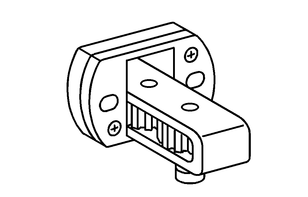

904 589 04 63 00
Turning device
715 589 00 37 00
Pliers
Henviste dokumenter
- ah0000n000101a Oplysninger om selvlåsende bolte og møtrikker
- ah1440n000101a Oplysninger om anvendelse og håndtering af AdBlue samt dets stofegenskaber
- ah1800n010101ha Oplysninger om motorolie
- ah6080n000301a Oplysninger om tipning af førerhus
- ar0100w2410j
- ar0110w240001j
- ar1322w1202j
- ar2020w3865j
- ar2020w3865jd
- ar2020w7450j
- ar2660w726001j Af-, påmontering af ledninger hydraulisk-pneumatisk-gearskifte (HPS) på motor
- ar4625w3300c Styretøjs udluftes
- ar4910w5530e
- ar8057w0010c Programmering af transpondernøgle
- as0000z000501a Fare for ulykke ved automatisk igangsætning når motoren kører. Fare for personskade på grund af knusning og forbrænding, hvis der arbejdes mens motoren startes eller kører
- as1440z000101a Fare for forbrænding og skoldning ved arbejde på AdBlue-rør og dermed forbundne komponenter. Fare for personskade på hud og øjne ved håndtering af AdBlue. Fare for forgiftning ved indtagelse af AdBlue
- as2000z000101a Risiko for skoldningsskader på hud og øjne pga. sprøjtende, varm kølervæske. Risiko for forgiftning ved indtagelse af kølervæske
- as4700z000101a Fare for eksplosion ved tænding, fare for forgiftning ved indånding og indtagelse af brændstof samt fare for hud- og øjenskader ved kontakt med brændstof
- as6080z000101a Fare for personskade ved fastklemning og knusning, når førerhuset tippes