Programmed Repairs Engine 102 2 E-E Carburetor Combustion IVb
14 Intake manifold, exhaust manifold
|
Fault: |
Possible causes
1. Rear stud bolt on cylinder head for attaching exhaust manifold loose or fractured.
2. Exhaust manifold leaking at side of cylinder head .
1st cause
Rear stud bolt on cylinder head for attaching exhaust manifold loose or fractured.
Remedy
When performing repairs, install improved stud
bolts, part no. 102 990 03 05.
Identification: black-bonderized (was yellow-chromatized).
Tightening torque: 273 Nm (was 21 Nm).
2nd cause
Exhaust manifold leaking at side of cylinder head.
Remedy
When performing repairs, install exhaust manifold gasket, part no. 117 142 00 60, of engine 117.963. Re-work mounting hole for stud bolt when performing this step.
Fault: Front passenger footwell heats up considerably as a result of catalytic converter. |
Remedy
1. Check clearance of heat shield (above catalytic converter) to vehicle floor.
Specification: 8-10 mm; adjust clearance if necessary (see also Group 49).
2. Lay glass fibre mat part no. 000 989 18 10, (only available as square meter matting) below foot mat.
Note
Model 124 RÜF/KAT: since 07/88 glass fibre mat fitted as standard in front passenger footwell.
Production breakpoint as of
Vehicle ident. end no. A 798379
B 082239
Fault: Exhaust manifold with ball flange fractured or twisted. |
Remedy
Install exhaust manifold, part no. 102 140 11 09, with new collar nuts and bolts 129 990 03 10.
15 Electrical system engine (ignition system)
Fault: |
Cause
Crankshaft position sensor (L5) for activating ignition system occasionally has open circuit or short to ground.
Test crankshaft position sensor (L5) (15-540).
Fault: Loud knocking noises from engine compartment in the area of ignition coil. |
Cause
Iron cores of Bosch ignition coils poorly bonded. This results in knocking noises at the ignition coil when the engine is running. This fault relates to ignition coils with production date FD 845-847.
Remedy
Install ignition coils with production date prior to FD 845 or after FD 847.
Fault: Engine cuts out when accelerating. Ignition point varies greatly (jumps). |
Cause
An excessively rough surface of the segments at the flywheel results in irregularities in the voltage pattern of the position sensor. On Bosch EZL electronic ignition control units this can cause undefined ignition point levels.
Remedy
Install Siemens ignition control units, part no.
006 545 41 32, and install new position sensor as a test.
If this does not rectify the fault, replace flywheel as segment faults may exist.
Fault: |
Cause
Poor fuel quality, engine oil consumption, incorrect ignition timing and deposits in combustion chamber.
Remedy
1. Test ignition point.
2. Examine combustion chamber for signs of coking and check oil consumption. Run engine hot on the chassis dynamometer, allow to coast to a stop and switch off. After approx. 10 minutes, illuminate the combustion chamber. If this reveals that the engine is consuming oil, conduct measures to counter oil consumption and rectify the coking of the combustion chamber.
3. If the measures described above do not prove successful, a modified ignition control unit may be installed following consultation with the warranty department.
Part no. of ignition control units
1) A conversion is necessary on vehicles prior to 09/88 (15-545)
Engine | Bosch control unit | Siemens control unit |
102.922 102.924 | 006 545 52 32 1) | 006 545 53 32 1) |
30 Accelerator control
Fault: |
Affected
All vehicles of models 124, 201 with manual transmission in LHD version.
Remedy
Adjust accelerator control (see 30-300,
or 30-330).
Part no.
Model | 124 | 201 |
Accelerator pedal lever | 124 300 04 25 | 201 300 09 25 |
Bearing | 124 301 04 18 | 201 301 03 18 |
Stop | 124 300 01 41 | 124 300 01 41 |
Production breakpoint: 11/88
Model | Vehicle ident. end no. |
124 | A 907 056 F 096 908 |
201 | A 473 115 F 576 183 |
47 Fuel system
Fault: Splashing noises model 124 Station Wagon (T-model) |
Remedy
Install fuel tank, part no. 124 470 57 01, with soundproofing shell.
Recognition feature:
4 mm dia. hole in left, rear edge.
Production breakpoint as of vehicle
ident.end no. F 022 693 (October 1986).
Fault: Smell of fuel in trunk and loud splashing noises in fuel tank. Model 201 with plastic fuel tank. |
Remedy
Install sheet steel fuel tank.
49 Exhaust system
Fault: Vehicle heats up at front right in interior (foot well), model 201. |
A. Shield at front right main floor
Cause
Insufficient clearance at front right frame floor between exhaust shield and frame floor.
Note
Sufficient clearance must exist between the exhaust pipe shield and the frame floor to avoid the floor heating up and to ensure proper air circulation.

Remedy
1. Check clearance between exhaust pipe and shield.
Specification: approx. 15 mm
Clearance <15 mm
Align shield upward on both sides and re-tighten bolts on shield.
Clearance >15 mm
Enlarge clearance between frame floor and
shield by 5 mm, see steps 2-8.
2. Unscrew rear engine support from body.
168-28970

3. Detach exhaust system, lower and secure with a V-belt.
4. Remove shield and clean.
5. Examine undersealing in the area of the shield and repair if necessary.
126-27956
6. Stick 5 mm spacers (e.g. M6 nut) to the
elevation at the mounting points of the shield
(e.g. with MB-Universal Sealant) and screw on
shield with longer self-tapping screws
(BZ 4.813).
7. Attach exhaust system and install engine support at the body.

8. Check front right foot mat, insulation material at vehicle floor and air duct for deformation and replace if necessary.
168-28969
Operation texts and time allowed
Measuring clearance between exhaust pipe and shield, determining condition
02-4908/01
Removing shield at front right main floor, installing (after inspecting)
02-4909 /01
Partially replacing insulation material in front right footwell (after inspecting)
02-4910/01
B. Shield in front right engine compartment

a) Examining
Check which version of the shield is installed.
Short shield (arrow)
(ends below forked member)
149-28206/1
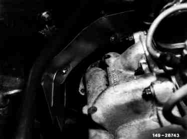
Long shield
(ends below forked member)
149-28743
Note
The work described below should only be performed on vehicles with the short shield. Vehicles with the long shield or the intermediate version, both recognizable from the mounting bolts on the forked member, are not affected by this work.

b) Procedure
1. Remove air cleaner.
2. Shorten shield of present standard version
(201 628 10 71). This is necessary because the shield installed remains in the vehicle.
a=15 mm
b=80 mm
c=80 mm
d=45 mm
Note
To avoid having to mark off each individual metal plate, we recommend using a shortened shield as a template for all others.
149-28739/1
3. If the paintwork has been damaged as a result of radiated heat (shaded area of illustration), roughen damaged points and touch up with a brush in matching colour of the car.
3.1 Should corrosion have occurred in isolated cases at the shaded area, also examine the underside of the forked member with a mirror.
149-28206/1
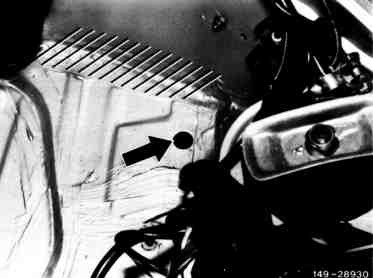
3.2 Remove battery; examine the area in the
battery compartment shown shaded and also the weld seam (illustration).
3.3 Clean corroded points mechanically, coat
first of all with MB primer filler with hardener
(mixing ratio 2:1) with a brush and after 5 min-
utes apply a good final coat. After a further
5 minutes, seal the weld seam within the battery compartment and at the engine compartment side with MB-Body Sealant, 001 989 63 20, and smooth with a brush dipped in cleaning petroleum. MB-2K top coat as for the primer coats. If car has metallic finish, coat only base paint.
149-28930
Thoroughly protect points on which work was performed and also cavity below the battery with protective wax (figure, arrow).
3.4 Install battery.
4. Examine coating of the brake line; replace damaged brake line.
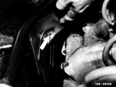
5. Align shortened shield at forked member, mark front hole (arrow) and drill hole with an angled power drill.
149-28740

149-28738
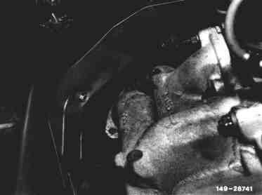
6 Install shield with the front self-tapping screw and punch rear hole with an angled power drift; the exhaust manifold can be used as a support when performing this step.
7 Screw in rear self-tapping screw.
8 Install air cleaner.
149-28741
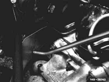
149-28742
Parts.
Designation | Part no. |
Shield | 201 682 10 71 |
Self-tapping screws (2 of) | 126 990 07 36 |
Operation text and time allowed
Installing shield
02-4907/01
Touching up damage to paintwork
02-9804/01
Eliminating corrosion, applying primer filler, sealing weld seam, applying cover paint, applying protective wax and removing/installing battery.
02-9805/01
Fault: Irregular, loud crackling or rustling after switching off engine after driving fast. |
Cause
As a result of the design of the front silencer in two-shell design and the high thermal load, stresses are produced during cooling down which cause this noise. A further cause is the high level of heat radiated by the front silencer to the shield.
Remedy
A remedy is not possible at the current state of engineering knowledge. The fault has no affect on the service life of the exhaust system.