07.2-160 Cleaning carburetor (carburetor cover removed)
Operation no. of operation texts and work units or standard texts and flat rates 07-6101 |

1073-16024
54 | Manipulation security plug |
56 | Float |
58 | Float needle |
59 | Float shaft |
61 | Actuating rod |
62 | Compression spring |
80 | Torsion spring |
84 | Adjusting screw |
85 | Holding ring |
95 | Actuating rod |
103 | Connector |
105 | Holding ring |
107 | Throttle valve actuator bracket |
108 | Protective sleeve |
2 | Gasket |
3 | 2nd stage aneroid cell |
5 | Spring plate |
8 | Carburetor cover |
9 | Carburetor body |
34 | Idle fuel nozzle |
36 | Plastic plate |
38 | Carburetor cover gasket |
39 | Mixture adjusting screw |
43 | 1st stage main nozzle |
44 | 2nd stage main nozzle |
45 | Fuel cutoff closing plate |
48 | 2nd stage pre-atomizer |
53 | 1st stage pre-atomizer |
122 | Compression spring |
124 | Plug |
125 | Locking element |
126 | Plastic bush |
127 | Vacuum hose |
128 | Filter strainer |
129 | Ground cable |
130 | Holding plate |
R8/1 | 2 E-E carburetor heater |
R24 | Throttle valve potentiometer |
Y18 | Float chamber vent valve |
Y22/1 | Choke actuator |
Y22/2 | Throttle valve actuator |
109 | Return spring |
110 | Bracket |
111 | O-ring |
112 | Retaining plate |
113 | Fastening screw |
114 | Hexagon nut |
115 | Spring lock washer |
116 | Gasket |
117 | Fuel hose |
118 | Hose strap |
119 | Gas separator |
120 | Valve plate |
121 | Spring holder |
Cleaning carburetor
Carburetor | remove, install (07.2-156). |
Carburetor | clean inside and outside. |
Carburetor cover | remove, install (07.2-158). |
Carburetor nozzles | clean (refer to instruction). |
Float level | check with shop-made gauge (refer to inspection instruction). |
Idling speed | test (07.2-100), specification: 700 - 800. |
Idle exhaust emissions level/lambda control | test, adjust (07.2-100). Idle exhaust emissions level: 1.00.5 CO (RÜF) Lambda specification: 5010 % (KAT) |
Test and adjusting data
Carburetor components 1) | 1st stage | 2nd stage |
Main nozzle | X 112.5 | X 127.5 |
Air correction nozzle (with mixing pipe) | 92.5 | 70 |
Idle fuel nozzle | X 50 | - |
Transition fuel nozzle | - | 60 |
Nozzle needle, idle air correction | 5 | - |
Float level | 27.51.0 mm | |
Float weight | 7.90.5 g | |
1) Up to carburetor no. 002 070 43 04 main nozzle 1st stage 110, 2nd stage 135, transition nozzle 70.
Shop-made tool

Gauge for measuring float level
1074-13663

Note
Cleaning carburetor nozzles and passages
1 Remove screws (arrows). Swivel closing plate (45) for fuel cutoff through 180 °C to gain access to all the nozzles.
107-32278
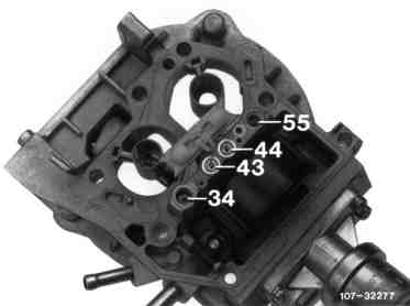
2 Unscrew main nozzle (43) for 1st stage, main nozzle (44) for 2nd stage, idle fuel nozzle (34). Blow nozzles and all accessible passages clear with compressed air.
A screwdriver should be ground accordingly for installation in order to avoid damaging the nozzles.
3 Screw in all nozzles again in the correct order. Move back closing plate (45) and fit screw with sealing ring to passage for idle fuel nozzle. Install screw plug with tapered seal to passage for 2nd stage transition fuel nozzle.
107-32277
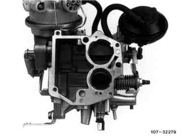
4 Blow clear all accessible passages in the carburetor body with compressed air.
107-32279

5 Check float level with gauge.
The valve pin (1) of the float needle must not compress during the measurement as a result of the float weight. For this reason, tilt carburetor cover approx. 30° when performing the measurement.
The float level cannot be adjusted. If a variation from the specification exists, install new float needle or new float.
107-32275

h Float level reference size
1 Valve pin
1074-13661

6 Check setting in full load enrichment tube, adjust if necessary.
The full load enrichment tube (49) should be pointing vertically to the centre of the pre-atomizer (53). The distance between pre-atomizer and enrichment tube should be
13.51.0 mm.
If necessary, alter direction and position of enrichment tube by bending accordingly.
107-32266