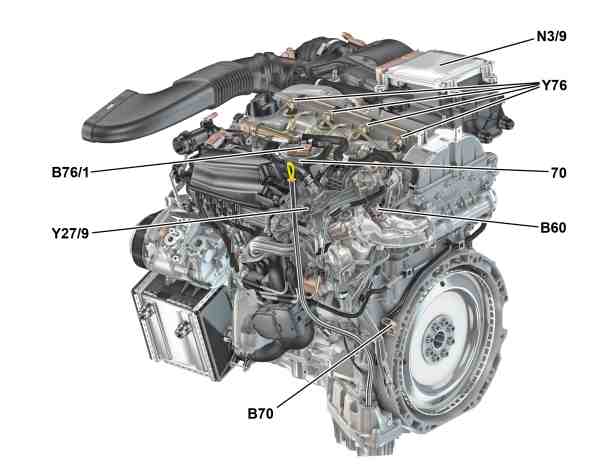
View of engine from rear left |
N3/9 | CDI control unit |
P07.16-3962-76
Location
The CDI control unit is on the air filter housing.
Tasks
The CDI control unit performs the following tasks:
Controlling the engine basic functions
Reading in of signals
Evaluation of input signals
Output of signals and actuation of components
The CDI control unit operates in an electrical network of sensors and actuators to form the engine management system for engine 651. The CDI control unit also acts as the interface (gateway) between the three connected CAN bus systems.
Controlling the engine basic functions
Fuel supply
Glow system
Injection quantity control
Electronic accelerator
Diagnosis and fault storage
Drive authorization system and immobilizer
Heat management
Exhaust gas recirculation
Exhaust treatment
Torque coordination
ECO start/stop function
Reading in of signals
Input signals are read in over the following connections:
Direct line
Drive-LIN (LIN C1)
Engine CAN (CAN C)
Drive train CAN (CAN C1)
Drive train sensor CAN (CAN I)
Evaluation of input signals
The input signals that have been read in are evaluated by the integrated microprocessor and the affected components are then actuated.
Output of signals and actuation of components
Initial parameter are output over the following connections:
Direct line
Drive train LIN
Engine CAN
Drive train CAN
Drive train sensor CAN
The electronic ignition lock control unit (N73) is the central interface (Gateway) for exchanging the function-relevant data of the control units that are connected to the various CAN bus systems.
Input factors and initial parameters for the following components are read in or output over direct lines by the CDI control unit and are needed by the engine management:
Input factors over a direct line | Initial parameters over a direct line | Supplemental information |
Terminal 15 | – | – |
Circuit 30 (fused) | – | – |
Circuit 31 | – | – |
Circuit 87 | – | – |
Engine oil temperature sensor (B1) | – | – |
Hot film mass air flow sensor (B2/5) | – | – |
Intake air temperature sensor (B2/5b1) | – | – |
High pressure fuel pressure sensor (B4/6) | – | Fuel high-pressure circuit |
Boost pressure sensor (B5/1) | – | – |
Low-pressure turbocharger boost pressure sensor (B5/4) | – | – |
Camshaft Hall sensor (B6/1) | – | – |
Coolant temperature sensor (B11/4) | – | – |
Exhaust gas recirculation temperature sensor (B16/14) | – | – |
Temperature sensor upstream of SCR catalytic converter (B16/15) | – | For code U77 (BlueTec (SCR) diesel exhaust treatment) |
Charge air temperature sensor (B17/8) | – | – |
Temperature sensor upstream of charge air cooler (B17/11) | – | – |
Temperature sensor upstream of catalytic converter (B19/7) | – | For code U77 (BlueTec (SCR) diesel exhaust treatment) |
Temperature sensor upstream of diesel particulate filter (B19/9) | – | For code 474 (Diesel particulate filter) |
Temperature sensor upstream of ATL (B19/11) | – | – |
DPF differential pressure sensor (B28/8) | – | For code 474 (Diesel particulate filter) |
Pressure sensor downstream of air filter (B28/11) | – | – |
Accelerator pedal sensor (B37) | – | – |
Fuel temperature sensor (B50) | – | – |
Clutch pedal sensor (B53/1) | – | with manual transmission |
Exhaust pressure sensor (B60) | – | – |
Crankshaft Hall sensor (B70) | – | – |
Manual transmission main shifter shaft position sensor (B79/3) | – | with manual transmission |
– | Starter circuit 50 relay (K40/8kH) | – |
Circuit 87M relay (K40/8kN) | Circuit 87M relay (K40/8kN) | – |
Engine compartment circuit 15 relay (K40/8kG) | – | – |
Oxygen sensor upstream of catalytic converter (G3/2) | Oxygen sensor upstream of catalytic converter (G3/2) | – |
Throttle valve actuator (M16/6) | Throttle valve actuator (M16/6) | – |
– | Intake port shutoff actuator motor (M55) | – |
Supplemental Restraint System control unit (N2/10) | – | – |
– | Fuel system control unit (N118) | – |
– | Vent line heater element (R39/1) | – |
– | Coolant thermostat heating element(R48) | – |
Oil level check switch (S43) | – | – |
– | Exhaust gas recirculation actuator (Y27/9) | – |
– | Boost pressure control pressure transducer (Y31/5) | – |
– | Pressure regulating valve (Y74) | – |
– | Cylinder 1 fuel injector (Y76/1) | – |
– | Cylinder 2 fuel injector (Y76/2) | – |
– | Cylinder 3 fuel injector (Y76/3) | – |
– | Cylinder 4 fuel injector (Y76/4) | – |
– | Exhaust gas recirculation cooler bypass switchover valve (Y85) | – |
– | Exhaust flap switchover valve (Y93) | – |
– | Quantity control valve (Y94) | – |
– | Actives engine mount on the left (Y123) Actives engine mount on the right (Y123/1) | With 4MATIC |
– | Engine oil pump valve (Y130) | – |
– | Oil spray nozzle shutoff valve (Y131) | – |
– | Coolant pump switchover valve (Y133) | – |
Input and output signals for the following assembly parts and control units are transmitted or received by the CDI control unit via the LIN or CAN and are needed by the engine management system:
Input factors via the drive-LIN (LIN C1) | Initial parameters via the drive-LIN (LIN C1) | Supplemental information |
Alternator (G2) | Alternator (G2) | – |
Glow output stage (N14/3) | Glow output stage (N14/3) | – |
Input factors via drive train CAN (CAN C1) | Initial parameters via drive train CAN (CAN C1) | Supplemental information |
Fuel system control unit (N118) | Fuel system control unit (N118) | – |
Powertrain control unit (N127) | Powertrain control unit (N127) | – |
Fully integrated transmission control unit (Y3/8n4) | Fully integrated transmission control unit (Y3/8n4) | With CODE 427 (7G-TRONIC) or with CODE 421 (9G-TRONIC) |
Input factors over engine CAN (CAN C) | Initial parameters via engine CAN (CAN C) | Supplemental information |
Instrument cluster (A1) | Instrument cluster (A1) | Via user interface CAN (CAN HMI), electronic ignition lock control unit (N73), chassis FlexRay (Flex E) and powertrain control unit (N127) |
Head unit (A26/17) | – | Via user interface CAN (CAN HMI), electronic ignition lock control unit (N73), chassis FlexRay (Flex E) and powertrain control unit (N127) |
Audio/COMAND control panel (A40/9) | – | Via telematics CAN (CAN A), head unit (A26/17), user interface CAN (CAN HMI), electronic ignition lock control unit (N73), chassis FlexRay (Flex E) and powertrain control unit (N127) |
Supplemental Restraint System control unit (N2/10) | – | Via user interface CAN (CAN HMI), electronic ignition lock control unit (N73), chassis FlexRay (Flex E) and powertrain control unit (N127) |
Front SAM control unit (N10/6) | – | Via interior CAN (CAN B), electronic ignition lock control unit (N73), suspension FlexRay (Flex E) and powertrain control unit (N127) |
Climate control control unit (N22/1) | – | Via interior CAN (CAN B), electronic ignition lock control unit (N73), suspension FlexRay (Flex E) and powertrain control unit (N127) |
Electronic Stability Program control unit (N30/4) | – | Via chassis FlexRay (Flex E) and powertrain control unit (N127) |
AIRMATIC control unit (N51/3) (for code 483 (ADVANCED AGILITY-package) and code 489 (AIRMATIC)) | – | Via chassis FlexRay (Flex E) and powertrain control unit (N127) |
Radar sensors control unit (N62/1) (with code (23P) Driving assistance package) | – | Via chassis FlexRay (Flex E) and powertrain control unit (N127) |
Left front door control unit (N69/1) | – | Via interior CAN (CAN B), electronic ignition lock control unit (N73), suspension FlexRay (Flex E) and powertrain control unit (N127) |
Electronic ignition lock control unit (N73) | Electronic ignition lock control unit (N73) | Via chassis FlexRay (Flex E) and powertrain control unit (N127) |
Steering column tube module control unit (N80) | – | Via chassis FlexRay (Flex E) and powertrain control unit (N127) |
Powertrain control unit (N127) | Powertrain control unit (N127) | – |
Diagnostic connector (X11/4) | Diagnostic connector (X11/4) | Via diagnostic CAN (CAN D), electronic ignition lock control unit (N73), chassis FlexRay (Flex E) and powertrain control unit (N127) |
Input factors via drive train sensor CAN (CAN I) | Initial parameters via drive train sensor CAN (CAN I) | Supplemental information |
NOx sensor control unit downstream of diesel particulate filter (N37/7) | NOx sensor control unit downstream of diesel particulate filter (N37/7) | For code U77 (BlueTec (SCR) diesel exhaust treatment) |
NOx sensor control unit downstream of SCR catalytic converter (N37/8) | NOx sensor control unit downstream of SCR catalytic converter (N37/8) | For code U77 (BlueTec (SCR) diesel exhaust treatment) |
AdBlue® control unit (N118/5) | AdBlue® control unit (N118/5) | For code U77 (BlueTec (SCR) diesel exhaust treatment) |
Structure
The housing of the CDI control unit is made of diecast aluminum and the cover is made of corrosion-proof sheet steel. The CDI control unit is water proof and dust proof.
The CDI control unit has an internal atmospheric pressure sensor.
Ground connection
The circuit 31 ground connection is made via several ground lines to the left major assembly compartment electronics ground point (W16/5).
Power supply
The CDI control unit is circuit 30 fused and also energized by circuit 87 when the ignition is switched on. In the operating voltage range it has both short-circuit protection and reversed polarity protection.
Power is supplied through several engaged parallel pins connected in parallel to relieve the electrical connections.
Assembly operations
Ensure before unplugging the connector on the CDI control unit that the ignition is switched off and processor run-on has ended. This is to prevent damage to the CDI control unit and save errors in the control units linked to the CAN.
Variants
The variants of the engine management, for exampled country and exhaust variants, are activated with XD over the variant coding.