AR33.10-D-0100A | Remove/install front axle | 10.11.11 |
FRONT AXLE 730.408 /410 in MODEL 901, 902
FRONT AXLE 730.409 in MODEL 902
FRONT AXLE 730.409 /413 in MODEL 903
FRONT AXLE 730.411 /414 in MODEL 904
FRONT AXLE 732.210 /211 /212 in MODEL 690.6
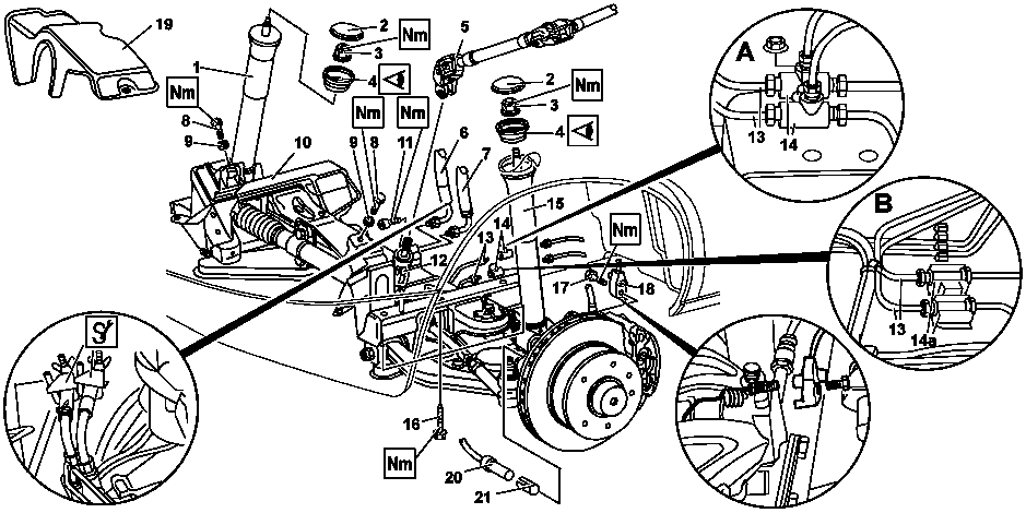
D33.10-0002-09
1 Right-hand shock-absorber strut
2 Shock-absorber strut attachment cover
3 Nut (M161.5)
4 Plate bearing for shock-absorber strut
5 Steering shaft universal joint
6 Steering pressure line
7 Steering return line
8 Engine mount bolt (M121.5)
9 Washer
10 Front axle
19 Turbocharger shield
20 ABS sensor
21 Clamping bush
A Version without ABS
B Version with ABS
11 Universal joint clamp bolt M8
12 Steering gear
13 Brake lines
14 T-pieces of brake lines
14a Screw couplings (with ABS)
15 Left shock-absorber strut
16 Front axle bolt (M121.5)
17 Brake pad wear indicator bolt (M6)
18 Brake pad wear indicator line
Modification notes
| Removing | ||
Danger! | Risk of poisoning caused by swallowing brake fluid. Risk of injury caused by brake fluid coming into contact with skin and eyes. | Only pour brake fluid into suitable and appropriately marked containers. Wear protective clothing and eye protection when handling brake fluid. | |
| Brake fluid notes | All models | |
1 | Remove front wheels | ||
2.1 | Unscrew brake lines (13) from the T-pieces of the brake lines (14) | Without brake system, antilock brake system ABS, code BB0 See magnified section A. | |
To avoid contamination, seal off line ends with plugs. | |||
| |||
2.2 | Unscrew brake lines (13) from screw couplings (14a) | With brake system, antilock brake system ABS, code BB0 See magnified section B. | |
To avoid contamination, seal off line ends with plugs. | |||
| |||
3 | Unscrew T-pieces of brake lines (14) | Without brake system, antilock brake system ABS, code BB0 | |
4 | Unscrew brake pad wear indicator line (18) from the bracket and detach plug | ||
5 | Remove ABS sensor (20) with clamping bush (21) | With brake system, antilock brake system ABS, code BB0 | |
6 | Detach universal joint of steering shaft (5) on steering gear (12) | ||
7 | Clamp off steering hoses on pressure line, steering return line (6, 7) | | |
| |||
8 | Unscrew pressure line, steering return line (6, 7) on steering gear (12) | To avoid contamination, seal off line ends with plugs. | |
| |||
9 | Detach upper shock-absorber strut mounting | ||
10 | Remove turbocharger shield (19) | With engine 602, 611, 612 | |
11 | Install engine support | ||
Engine support device, engine hoist | |||
12 | Unscrew engine mount bolts (8) | ||
13 | Detach front axle (10) from longitudinal frame member | ||
| |||
| Install | ||
14 | Mount front axle (10) on longitudinal frame member | Replace spring clamp plate nuts which have been removed. | |
| |||
| |||
| |||
15 | Attach steering shaft universal joint (5) to steering gear (12) | Model 901.0/3/4, 902.0/3/4, 903.0/3/4, 904.0/3/4 | |
Model 901.6, 902.6, 903.6, 904.6, 690.6 | |||
| |||
16 | Lower engine and install engine mount bolts (8) | Ensure they are properly seated in the bores in the front axle housing. | |
Engine 601, 602 | |||
Engine 111 | |||
Engine 611, 612, 647 | |||
17 | Remove engine support | ||
18 | Install turbocharger shield (19) | With engine 602, 611, 612 | |
19 | Screw on pressure line, steering return line (6, 7) on steering gear (12) | | |
| |||
20 | Detach clamps on steering hoses of pressure line, steering return line (6, 7) | | |
| |||
21 | Attach upper shock-absorber strut mounting | Replace nuts (3). | |
| |||
22.1 | Screw brake lines (13) loosely onto T-pieces, tighten T-pieces and then tighten brake lines | Without brake system, antilock brake system ABS, code BB0 See magnified section A. | |
| |||
22.2 | Attach brake lines (13) to screw couplings (14a) | with brake system, antilock brake system ABS, code BB0 See magnified section B. | |
| |||
23 | Screw brake pad wear indicator line (18) onto the bracket and connect plug | Ensure that the cable is routed free of chafing. | |
| |||
24 | Install ABS sensor | With brake system, antilock brake system ABS, code BB0 | |
MB silicone grease | |||
25 | Bleed brake system | ||
26 | Fit front wheels | ||
Danger! | Risk of accident caused by vehicle starting off by itself when engine is running. Risk of injury caused by contusions and burns during starting procedure or when working near the engine as it is running | Secure vehicle to prevent it from moving by itself. | |
27 | Turn the steering several times from stop to stop | To bleed the steering system. | |
28 | Check steering oil level | Adjust to correct level if necessary | |
| Check and correct power steering fluid level |
Engine mounts, engine supports
Number | Designation | Engine 602.980 | Engine 601.943 | ||
BA22.10-N-1002-01A | Engine support on front end mount | Nm | 83 | 83 | |
Engine mounts, engine supports
Number | Designation | Engine 111.979 | Engine 111.984 | ||
BA22.10-N-1002-01H | Engine support on front end mount | Nm | 83 | 83 | |
Engine mounts, engine supports
Number | Designation | Engine 611.981/ | Engine 612.981 | Engine 647.981 | |
BA22.10-N-1002-01L | Bolt, engine bracket to front engine mount | Nm | 83 | 83 | 83 |
Front axle steel suspension
Number | Designation | Model 901, 902, 903, 904 with front axle 730.4 | Model 690.6 with | |||
BA32.20-N-1001-01A | Bolt, lower spring clamp plate to front axle beam | M121.5 | Stage 1 | Nm | 130 | 130 |
Stage 2 | ° | - | - | |||
M8 | Nm | - | - | |||
M10 | Nm | 65 | 65 | |||
Front axle shock-absorber strut
Number | Designation | Model 901 with front axle 730.408/410 | Model 902 with front axle 730.408/409/410 | |||
BA32.25-N-1001-02A | Nut, damper strut to body | M161.5 | Nm | 100 | 100 | |
Front axle shock-absorber strut
Number | Designation | Model 903 with front axle 730.409/413 | Model 904 with front axle 730.411/414 | |||
BA32.25-N-1001-02A | Nut, damper strut to body | M161.5 | Nm | 100 | 100 | |
Front axle shock-absorber strut
Number | Designation | Model 690.6 with front axle 732.210/211/212 | |||
BA32.25-N-1001-02A | Nut, damper strut to body | M161.5 | Nm | 100 | |
Front axle carrier
Number | Designation | Front axle 730.4 in model 901, 902, 903, 904 | Front axle | |||
BA33.10-N-1001-01B | Bolt, front axle carrier to longitudinal frame member | M121.5 | Nm | 125 | 125 | |
Brake hoses, brake lines
Number | Designation | Model 690.6, 901, 902, 903, 904 without code BB0 | Model 690.6, | ||
BA42.10-N-1001-04A | Brake line threaded connection | M101 | Nm | 14 | 14 |
Front axle brake caliper
Number | Designation | Models | Model 904 | Model 690.6 | ||
BA42.10-N-1003-10A | Bolt, wear indicator to brake caliper | M6 | Nm | 10 | 10 | 10 |
Steering wheel, jacket tube, steering shaft
Number | Designation | Model | Model | ||
BA46.10-N-1003-05C | Universal joint to steering gear shaft | Nm | 24 | 24 | |
Steering gear
Number | Designation | Models | ||
BA46.20-N-1001-01C | High-pressure expansion hose to steering gear | Nm | 37 | |
BA46.20-N-1002-01C | Return flow line to steering gear | Nm | 37 | |


000 589 40 37 00
Circuit
Circuit
Set of stop plugs
Assembly device
129 589 00 91 00
000 589 54 37 00
906 589 00 62 00
Repair materials
Number | Designation | Order number |
BR00.45-Z-1019-06A | ABS sensor grease | A 000 989 62 51 10 |
Odkazované dokumenty
- ah4250p000101a Upozornění k brzdové kapalině
- ap4600d4611a Kontrola, vyrovnání hladiny oleje servořízení
- ar3310d010002a
- ar3310d010004a
- ar3310d010005a
- ar4010d1100a Demontáž, montáž kol
- ar4210d0010a
- ar4230d062001a
- ar4610d730001a
- ar4610d730001b
- as0000z000501a Nebezpečí úrazu při samovolném rozjetí vozidla při běžícím motoru. Nebezpečí poranění pohmožděním a popálením při výkonech prováděných během startování nebo při běžícím motoru
- as4250z000101a Nebezpečí otravy při požití brzdové kapaliny. Nebezpečí poranění při kontaktu brzdové kapaliny s kůží a očima