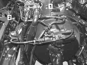
1 | Compressed-air line |
2 | Control line |
G13.30-3141-01

1 | Compressed-air line |
2 | Control line |
3 | Coolant lines |
4 | Screw |
5 | Compressor |
G13.30-3142-81

5 | Compressor |
6 | Gear |
7 | O-ring |
8 | O-ring |
9 | Fitting |
10 | Fitting |
G13.30-3143-03
Warning | Risk of accident from vehicle starting off by itself when engine running. Risk of injury (bruises and burns) resulting from working on the engine while it is being started or when it is running. | Secure vehicle to prevent it from starting off by itself. Wear closed and snug-fitting work clothes. Do not touch hot or rotating parts. | |
Warning | Risk of injury to skin and eyes suffering scalding from contact with hot coolantspray. Risk of poisoning from swallowing coolant. | Do not open cooling system unless coolant temperature is below 90 °C. Open cap slowly and release the pressure. Do not pour coolant into beverage containers. | |
Caution | Risk of injury to skin and eyes due to handling of engine oil. Risk of poisoning caused by swallowing engine oil | Wear protective gloves, protective clothing and safety glasses. | |
Topical note | Notes on avoiding damage through contamination and foreign objects | ||
Topical note | Notes on self-locking nuts and bolts | ||
Topical note | Notes on coolant | ||
Note on calculation of tightening torque when using insertion or socket tools with various effective lengths | |||
| Remove/install | ||
1 | Drain off coolant. | ||
| |||
2 | Tilt cab to repair position. | ||
Installation: Only tilt back cab after the leak test. | |||
3 | Remove ground line of battery. | ||
4 | Remove compressed-air line (1) between the compressor (5) and the first separating point. | Installation: Check compressed-air line (1) for carbonization. | |
If problems exist, | |||
| |||
Replace air line (1) and all carbonized parts. | |||
Union nut, compressed air line to compressor fitting | |||
5 | Seal fitting (9) on the compressor (5) with a suitable stop plug. | Plug | |
6 | Completely remove control line (2). | Union nut, control line to compressor | |
7 | Seal connection fittings of the control line (2) with suitable stop plugs. | Record plug | |
8 | Remove power steering pump. |
| |
Installation: Only purge steering equipment after pouring in the coolant. | |||
9 | Release coolant lines (3), remove, and collect escaping coolant. | ||
10 | Remove screw (4) from the fuel line bracket. | ||
11 | Remove screws of the compressor (5) from the timing case. | The compressor (5) is fastened with four screw/bolts on the timing case. | |
Bolt, compressor to timing case | |||
12 | Remove compressor (5) and collect escaping engine oil. | Installation: First insert the rear upper screw/bolt in the bore on the compressor (5), then place the compressor (5) on the timing case. | |
13 | Remove O-rings (7, 8) from the compressor (5). | Installation: Install new O-rings (7, 8). | |
14 | Remove fittings (9, 10) from the compressor (5). | Only if compressor (5) was replaced or fitting (9, 10) is leaky. | |
Fitting to compressor | |||
15 | Remove fittings of the coolant lines (3) from the compressor (5). | Only if the compressor (5) is replaced or the fittings for the coolant lines (3) are leaky. | |
Fitting, coolant line to compressor | |||
16 | Remove fitting of the control line (2) from the compressor (5). | Only if compressor (5) was replaced or fitting of control line (2) is leaky. | |
Fitting to compressor | |||
| Check | ||
17 | Check gearwheel (6) for damage and wear. | If problems exist, | |
| |||
replace gearwheel (6). | |||
18 | Check counter gear of the gearwheel (6) in the timing case for damage. | If problems exist, | |
| |||
replace counter gear. | |||
19 | Install in the reverse order. | ||
| Check | ||
20 | Check engine oil level on the instrument cluster. | ||
| |||
If problems exist, | |||
| |||
Correct engine oil level . | |||
Engine oil | |||
21 | Start engine and perform an engine test run. | ||
22 | Check all connections and lines on the compressor (5) for leak tightness. | Visual inspection. | |
23 | Switch off engine. | ||
24 | Check/correct coolant level. | ||
|


963 589 01 91 00
Plug
129 589 00 91 00
Record plug
Odkazované dokumenty
- ah0000n000101a Upozornění k samopojistným šroubům a maticím
- ah0000n500001h Upozornění k zamezení poškozením kvůli znečistění a výskytu cizích těles
- ah0000p001501cw Pokyny pro výpočet utahovacího momentu při použití zasouvacích nebo násuvných nástrojů s různými činnými délkami
- ah2000n208001a Upozornění ke chladicí kapalině
- ap1800g010107u Požadavek stavu hladiny motorového oleje na displeji
- ap2000g2010u Zkontrolovat, vyrovnat hladinu kapaliny chladicího systému motoru. Zkontrolovat,vyrovnat podíl ochrany proti korozi/mrazu
- ap2000g2080u Výměna chladicí kapaliny
- ar0510g4660u
- ar1330g7044u
- ar4630g0500uv
- ar5410g0003ug
- ar6080g0005b
- ar6080g0005b
- as0000z000501a Nebezpečí úrazu při samovolném rozjetí vozidla při běžícím motoru. Nebezpečí poranění pohmožděním a popálením při výkonech prováděných během startování nebo při běžícím motoru
- as1800z000101a Nebezpečí poranění očí a pokožky stykem s motorovým olejem. Nebezpečí otravy při požití motorového oleje
- as2000z000101a Nebezpečí poranění kůže a očí opařením vystřikující, horkou chladicí kapalinou. Nebezpečí otravy při požití chladicí kapaliny