AR01.10-P-2500GF | Remove/install engine with front axle carrier | 10.11.11 |
ENGINES 166.940 /960 /990 /995 in MODEL 168

P01.10-2434-09
1 Air intake scoop
2 Air intake duct
3 Resonator (only engine 166.960/990)
4 Crankcase breather line
5 Vacuum line
6 Coolant hose
7 Exhaust system
8 Seal (vehicles up to 28.2.01)
9 Spring (vehicles up to 28.2.01)
10 Screw/bolt (vehicles up to 28.2.01)
50 Coolant hose
51 Coolant hose
52 Coolant hose
53 Coolant hose
54 Oil lines (for transmission 722.7)
62 Coolant hose
N3/5 ECM [MSM] control unit
11 Clamp (vehicles from 1.3.01)
12 Vehicle wiring harness plug
13 Coolant hose
14 Coolant hose
15 Fuel line
16 Vacuum line
17 Vacuum line
49 Coolant expansion reservoir

P01.10-2159-09
18 Clutch hose
19 Sealing ring
20 Fuse
21 Shift cable
22 Shift cable
23 Coolant hose
24 Coolant hose
25 Positive line
26 Control line
55 Screw/bolt (for transmission 722.7)
56 Holder (for transmission 722.7)
57 Shift cable (for transmission 722.7)
58 Connector (for transmission 722.7)
Steering coupling with nut holder
27 Steering coupling
28 Steering shaft
29 Thrust piece
30 Screw/bolt
31 Collar nut

P14.30-2024-01
P46.10-2198-01
P14.10-2025-01
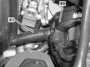
60 Air pump
61 Hose
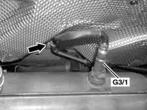
G3/1 O2 sensor downstream of catalytic converter
Steering coupling with nut holder
27 Steering coupling
28 Steering shaft
29 Thrust piece
30 Screw/bolt
59 Nut holder

P01.10-0347-09
32 Front axle carrier
33 Screw/bolt
34 Strut
35 Screw/bolt
36 Screw/bolt
37 Suspension strut
38 Rpm sensor connector for front axle
47 Poly-V belt
48 Front axle carrier removal device
A9 Refrigerant compressor
G2 Alternator
M1 Starter
39 Brake pad contact sensor connector
40 Floating caliper
41 Screw/bolt
42 Alternator harness
43 Starter wiring harness
44 Ground cable
45 Screw/bolt
| Remove/install | ||
Danger! | Risk of death caused by vehicle slipping or toppling off of the lifting platform. | Align vehicle between columns of lifting platform and position the four support plates at lifting platform support points specified by vehicle manufacturer. | |
1.1 | Unscrew oil drain screw from oil pan at automatic transmission and drain ATF | Only on vehicles fitted with transmission 722.7. Installation: Replace sealing ring. | |
| |||
2 | Drain coolant at radiator and crankcase | ||
3 | Disconnect battery ground line | ||
4.1 | Remove washer fluid reservoir | Only for vehicles with code (875) Heated windshield washer system. | |
5 | Detach ground cable at right front engine support | ||
6 | Remove air intake scoop (1), air intake hose (2) and resonator (3) | A resonator (3) is only installed for engine 166.960/990 | |
7 | Detach vacuum line (5) at intake manifold | ||
8 | Release and unplug vehicle wiring harness connector (12) on ECM [MSM] control unit (N3/5). Separate cable tie | Shown on vehicle up to 28.2.01 Release and disconnect connector (white arrow). | |
Danger! | Risk of explosion caused by ignition of flammable products, risk of poisoning caused by inhaling fuel vapors or swallowing fuel as well as risk of injury to skin and eyes exposed to fuel. | No fire, sparks, open flames or smoking. Wear protective clothing when handling fuel. | |
9 | Disconnect fuel line (15) at fuel distributor | Seal fuel line (15) with a suitable plug. | |
10 | Detach vacuum line (16) of purge valve | ||
11 | Detach vacuum lines (17) at intake manifold, detach along fuel rail and place to the side | ||
12.1 | Remove coolant hoses (13, 14) | Vehicles without a separate coolant expansion reservoir. Installation: Replace hose clamps. | |
12.2 | Remove coolant hoses (50, 52, 62) on coolant expansion reservoir (49), unlock striker on coolant expansion reservoir (49) (arrow) and remove coolant expansion reservoir (49). | On vehicles with a separate coolant expansion reservoir Installation: Replace hose clamps. | |
| Radiator with separate coolant expansion reservoir | Engine 166 in model 168 as of 1.6.99 | |
13 | Remove coolant hose (51) below on radiator and coolant hose (53) on the side on longitudinal member (arrow) | Installation: Replace hose clamps. | |
14 | Detach coolant hose (6) at coolant thermostat | Installation: Replace hose clamps. | |
15.1 | Detach oil lines (54) at oil cooler and seal with a suitable plug | Only models fitted with transmission 722.7. The oil cooler is integrated within the radiator. | |
| |||
16 | Remove heating feed and heating return flow coolant hoses (23, 24) | Installation: Replace hose clamps. | |
17 | Detach steering coupling (27) at steering shaft (28), take off thrust piece (29) | Installation: Replace self-locking collar nut (31) or nut bracket (59). | |
| |||
18 | Disconnect positive line (25) and control line (26) for power steering pump at left frame longitudinal member | ||
19 | Detach shift cables (21, 22) by turning locknuts counterclockwise, releasing them from the bracket and then unsnapping the shift cables from the ball joints | Installation: Ensure that shift cables (21, 22) are securely attached to the ball heads. | |
20.1 | Disconnect electrical connectors to turning angle sensors, expose electrical line and place to one side | Only on models fitted with automatic clutch system (code 421) | |
21.1 | Detach hose (61) at the air pump (60) | Only for vehicles from 1.3.01 | |
22 | Detach suspension strut (37) at suspension strut dome | Installation: Lead guide pin on suspension strut (37) into guides (arrow) on the suspension strut tower. | |
| |||
23 | Detach floating caliper (40) at steering knuckle, tie up in wheelhousing together with brake pads and connected brake hose | Installation: Replace self-locking bolts (41). | |
| |||
24 | Disconnect plug connection for brake pad contact sensor (39) and plug connection for front axle speed sensor (38) in top of wheelhousing; expose cable | The plug connection for brake bad contact sensor (39) is only installed at the front right. | |
25.1 | Remove collar clamp (11) and separate flange connection between catalytic converter (7) and exhaust system | In vehicles as of 1.3.01 | |
25.2 | Remove screw/bolt (10) and disconnect exhaust system flange connection (7) at catalytic converter | In vehicles up to 28.2.01 | |
Installation: Replace seal (8), check condition of flange connection rivet nut, if necessary | |||
Replace rivet nut of flange connection | |||
26.1 | Take cable of O2 sensor downstream of catalytic converter (G3/1) out of retaining clip (arrow) at underfloor and separate plug connection | Only for vehicles from 1.3.01 | |
Danger! | Risk of poisoning caused by swallowing brake fluid. Risk of injury caused by brake fluid coming into contact with skin and eyes. | Only pour brake fluid into suitable and appropriately marked containers. Wear protective clothing and eye protection when handling brake fluid. | |
27 | Remove locking element (20) and pull clutch hose (18) out of the transmission from below | Seal clutch hose (18) with a suitable plug. Installation: Replace sealing ring (19) and securing device (20). | |
| Brake fluid notes | All models | |
28.1 | Release the poly-V belt (47) and remove it from refrigerant compressor (A9) | Only on vehicles with code (580) Air conditioning or for USA Tempmatic | |
29.1 | Detach refrigerant compressor (A9) and attach it to the underbody with the connected refrigerant lines and electrical lines | Only on vehicles with code (580) Air conditioning or for USA Tempmatic | |
30 | Prepare front axle carrier removal fixture (48) | Risk of tipping during later lowering - note location of the adapter. Adapter modification required from model refinement package 03/2001 or VIN "WDB1680311J568590" . | |
Also from VIN "WDB1680311J568590" | |||
Jack assembly adapter gotis://A_25/35/49_03.0 | |||
31 | Align front axle carrier removal fixture (48) at front axle carrier (32) and fit evenly | Risk of tipping during later lowering. | |
Also from VIN "WDB1680311J568590" | |||
32 | Take off struts (34) at front axle carrier (32) and at underfloor | | |
33 | Take off wheelhousing liners on left and right at underfloor and fold down | To gain access to the rear screw/bolts (33). | |
34 | Unscrew screw/bolts (33) (8 pcs.) | | |
35 | Carefully lower engine together with front axle carrier (32) far enough to gain access to starter (M1) and alternator (G2) | Proceed with caution to avoid damaging coolant hoses, AC hoses and electrical wiring. | |
Installation: Guide (arrow) on the front axle carrier (32) must be inserted in the bore in the longitudinal member. | |||
36.1 | Unhook shift cable (57) from shift linkage, remove bracket (56) from transmission and take out of support (arrow). Unlock plug (58) on transmission (arrow) and detach | Only models fitted with transmission 722.7. | |
37 | Disconnect ground cable (44) together with fixture at oil pan | ||
38 | Remove starter wiring harness (43) on starter (M1) | Terminal 50 | |
Terminal 30 | |||
39 | Remove alternator wiring harness (42) on alternator (G2) | Circuit D+ | |
Circuit B+ | |||
40 | Carefully lower engine with front axle carrier (32) fully | Proceed with caution to avoid damaging coolant hoses, a/c hoses and electrical wiring. | |
41 | Install in the reverse order | ||
Danger! | Risk of accident caused by vehicle starting off by itself when engine is running. Risk of injury caused by contusions and burns during starting procedure or when working near the engine as it is running | Secure vehicle to prevent it from moving by itself. | |
42.1 | Check oil level in automatic transmission; fill with oil if necessary | Only on vehicles fitted with transmission 722.7. | |
43 | Bleed clutch operating system | ||
44 | Inspect cooling system for leaks |
Starter
Number | Designation | Engine | |
BA15.30-P-1002-01B | Cable to starter circuit 50 | Nm | 6 |
BA15.30-P-1003-01B | Cable to starter circuit 30 | Nm | 9 |
Alternator
Number | Designation | Engine 166.940/ | |
BA15.40-P-1001-01B | Cable to alternator terminal D+ | Nm | 6 |
BA15.40-P-1002-01B | Cable to alternator terminal B+ | Nm | 18 |
Radiator, coolant hoses
Number | Designation | Engine 166.940/ | |
BA20.20-P-1002-01C | Union nut, automatic transmission oil line to radiator | Nm | 25 |
Oil pan, automatic transmission
Number | Designation | Trans-mission 722.3 | Trans-mission 722.4/5/7 | |
BA27.10-P-1001-03A | Drain plug on transmission oil pan | Nm | 14 | 22 |
Suspension struts
Number | Designation | Model 168.006/ | |
BA32.25-P-1002-04A | Screw/bolt, suspension strut to suspension strut dome | Nm | 40 |
Front axle carrier
Number | Designation | Model 168 | ||
BA33.10-P-1001-01B | Screw/bolt, front-axle carrier to body | M 12 | Nm | 120 |
BA33.10-P-1003-01B | Strut bolt on front-axle carrier | M 10 | Nm | 60 |
Front axle brake caliper
Number | Designation | Model | ||
BA42.10-P-1001-10O | Self-locking bolt, brake caliper to steering knuckle | Nm | 115 | |
Steering shaft
Number | Designation | Model 168 | |
BA46.10-P-1002-01C | Screw/bolt, steering coupling to steering shaft | Nm | 20 |
Exhaust system
Odkazované dokumenty
- ah4250p000101a Upozornění k brzdové kapalině
- ar1322p1202gf
- ar1410p409501gf
- ar2000p1010gf
- ar2000p1142gf
- ar2520p0070gc
- ar2700p0101gc
- ar5410p0003a
- as0000z000501a Nebezpečí úrazu při samovolném rozjetí vozidla při běžícím motoru. Nebezpečí poranění pohmožděním a popálením při výkonech prováděných během startování nebo při běžícím motoru
- as0000z001001a Nebezpečí ohrožení života v případě sesunutí nebo překlopení vozu z dílenského zvedáku
- as4250z000101a Nebezpečí otravy při požití brzdové kapaliny. Nebezpečí poranění při kontaktu brzdové kapaliny s kůží a očima
- as4700z000101a Nebezpečí výbuchu při vznícení, nebezpečí otravy při vdechnutí a požití paliva inebezpečí úrazu v důsledku přímého doteku kůže a očí s palivem
- bt2030p000101gf