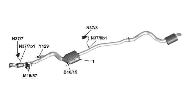
View of exhaust system |
N37/7 | NOx sensor control unit downstream of diesel particulate filter |
N37/7b1 | NOx sensor downstream of diesel particulate filter |
N37/8 | NOx sensor control unit downstream of SCR catalytic converter |
N37/8b1 | NOx sensor downstream of SCR catalytic converter |
P14.00-2139-75
Location
The NOx control units are screwed onto the underfloor. The NOx sensors are screwed into the exhaust system.
Task
The NOx sensors control units are supplied by the company "VDO Automotive AG".
The NOx sensors detect the NOx and the O2 concentration in the exhaust downstream of the DPF and the SCR catalytic converter and pass this information onto the NOx sensors control units in the form of voltage pulses. These control units process the information and transmit it via the drive train sensor CAN (CAN I) to the CDI control unit (N3/9).
Input and output signals
The NOx sensors control units evaluate the following input signals and send the corresponding output signals:
Direct input signals
CAN input signals from the CDI control unit
CAN output signals to the CDI control unit
Direct input signals
Terminal 87
CAN input signals from the CDI control unit
Diagnosis requests
CAN output signals to the CDI control unit
NOx concentration in the exhaust
O2 concentration in exhaust
Diagnostic data
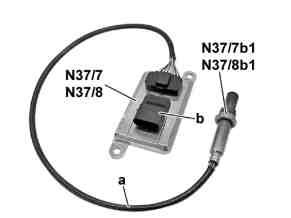
N37/7 | NOx sensor control unit downstream of diesel particulate filter |
N37/7b1 | NOx sensor downstream of diesel particulate filter |
N37/8 | NOx sensor control unit downstream of SCR catalytic converter |
N37/8b1 | NOx sensor downstream of SCR catalytic converter |
P14.40-2334-01
Body
Every NOx sensor (double chamber sensor with evaluation circuit) is inseparably connected via an 8-pin signal line with the respective NOx sensor control unit. An integral sensor heater which is controlled by the respective NOx sensor control unit ensures rapid readiness to operate of the NOx sensors.
Function
The active ceramic probe bodies consist of many layers with two reaction chambers. The oxygen (O2) in the exhaust is detected in the first chamber, as in an oxygen sensor.
To do this, a pump voltage is applied to the electrodes in the first chamber. This causes the O2 molecules to be split into double charged oxygen ions and then pumped out of or into the first chamber (depending on whether rich or lean exhaust is present) until a 450 mV voltage difference at the electrodes is reached. The oxygen concentration is calculated from the size of the required pump current "Ip1".
The nitrogen oxide is split at the ground electrode into nitrogen and oxygen in the second chamber if present.
The oxygen is pumped out if the chamber again.
The concentration of the nitrogen oxides in the exhaust is calculated from the resulting pump current "Ip2".
The voltage signals from NOx sensors are transmitted to the respective NOx sensor control unit and processed there. The NOx sensor control units send the NOx and the O2 concentration to the CDI control unit via drive train sensor CAN.

Schematic function diagram of the NOx sensor (double chamber sensors) |
1 | Diffusion gap 1 |
2 | Diffusion gap 2 |
3 | Solid electrolyte |
Ip1 | Pump current 1 |
Ip2 | Pump current 2 |
P07.04-2541-76