
Shown on model 204.0/2 without 4MATIC |
1 | Link rod |
1a | Nut |
2 | Electrical line |
3 | Line bracket |
4 | Cable tie |
5 | Bolts |
6 | Steering knuckle |
7 | Nut |
8 | Screw |
9 | Bolts |
10 | Cap |
40 | Suspension strut |
P32.25-2186-06
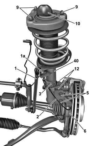
Shown on model 204.98 |
1 | Link rod |
1a | Nut |
2 | Electrical line |
3 | Line bracket |
5 | Bolts |
6 | Steering knuckle |
9 | Bolts |
10 | Cap |
12 | Clips |
40 | Suspension strut |
P32.25-2230-03

01 | Drift |
10 | Cap |
11 | Retaining clamp |
41 | Spring cup |
P32.25-2225-05
| Remove/install | ||
Danger ! | Risk of injury. Moving parts can pinch, crush or, in extreme cases even sever extremities. | No parts of the body or limbs should be within the operating area of the mechanism when the components are moving. | |
Danger ! | Risk of death caused by vehicle slipping or toppling off of the lifting platform. | Align vehicle between vehicle lift columns and position the four support plates at the vehicle lift support points specified by the vehicle manufacturer. | |
| Notes on self-locking nuts and bolts | ||
1 | Open engine hood and move to vertical position | MODEL 204 (except 204.3) | |
MODEL 172 | |||
MODEL 204.3, 207 | |||
2 | Remove left or right front wheel | MODEL 204, 207 | |
| |||
| MODEL 172 | ||
3 | Unscrew nut (1a) and press link rod (1) out of suspension strut (40) | MODEL 204 | |
MODEL 172 | |||
4 | Unclip electrical line (2) from line bracket (3) | ||
5 | Remove cable tie (4) on suspension strut (40) | Installation: Observe installation position and replace cable tie (4). | |
Pliers | |||
6.1 | Unclip line holder (3) from suspension strut (40) and place to one side | MODEL 207 except 4MATIC MODEL 172, 204.0/2/3 | |
6.2 | Open clip (12) and remove line bracket (3) from suspension strut (40) | MODEL 204.9 MODEL 207 with 4MATIC | |
7 | Detach electrical connection from suspension strut (40) | MODEL 172, 204, 207 | |
8 | Remove bolts (5) from steering knuckle (6) | MODEL 172 | |
MODEL 204.0/2/3, 207 except 4MATIC | |||
Model 204, 207 with 4MATIC | |||
9 | Unscrew nut (7) and pull out bolt (8) | Model 172, 204, 207 except 4MATIC | |
TYP 172 | |||
MODEL 204, 207 except 4MATIC | |||
10 | Press suspension strut (40) out of steering knuckle (6) | ||
11 | Remove bolts (9) from suspension strut tower | ||
| Bolt, suspension strut to suspension strut tower modified | ||
Model 204, 207 | |||
MODEL 172 | |||
12 | Press retaining clamps (11) of cap (10) together and remove suspension strut (40) | MODEL 204 | |
| Cap for front suspension strut modified | ||
Insert two punches (01) through the bores in cap (10) and compress the retaining clamp (11) until the catch hooks (arrows) on the spring cup (41) are unlocked. | |||
| Check | ||
13 | Check suspension strut (40) | The suspension strut (40) should be replaced in the event of damage. | |
14 | Install in the reverse order | ||
15 | Perform wheel alignment check | MODEL 172, 207 | |
MODEL 204 |
Suspension struts |
Number | Designation | MODEL 204.00/02/04/05/06/20/22/24/25/30/33/34/35 except CODE 483, MODEL 204.077/277, MODEL 204.377 except CODE P98 | MODEL 204.00/02/04/05/06/20/22/24/25/30/33/34/35 with CODE 483 | |||
BA32.25-P-1001-04M | Bolt, suspension strut to steering knuckle at top | M1445 | Stage 1 | Nm | 100 | 100 |
Stage 2 | ° | 90 | 90 |
Suspension struts |
Number | Designation | MODEL 204.00/02/04/05/06/20/22/24/25/30/33/34/35 except CODE 483, MODEL 204.077/277, MODEL 204.377 except CODE P98 | MODEL 204.00/02/04/05/06/20/22/24/25/30/33/34/35 with CODE 483 | |||
BA32.25-P-1002-04M | Bolt, suspension strut to steering knuckle at bottom | M1220 | Stage 1 | Nm | 70 | 70 |
Stage 2 | lösen | lösen | ||||
Stage 3 | Nm | 100 | 100 |

164 589 01 37 00
Pliers