
W26.50-1066-09
1 Locknut
2 Tapered roller bearing
3 Shim
4 Tapered roller bearing
5 Constant mesh gear 2
6 Tapered roller bearing
7 Synchronizer ring
8 Synchronizer cone
9 Thrust spring
10 Circlip
11 Sliding sleeve
23 Synchronizer cone
24 Thrust spring
25 Circlip
26 Sliding sleeve
27 Synchronizer body
28 Needle roller bearing
29 Thrust spring
30 Synchronizer cone
31 3rd gear wheel
35 Main shaft
12 Synchronizer body
13 Thrust spring
14 Synchronizer cone
15 Synchronizer ring
16 5th gear wheel
17 Socket
18 Needle roller bearing
19 Thrust plate
20 Needle roller bearing
21 4th gear wheel
22 Synchronizer ring

W26.50-0074-09
35 Main shaft
36 Needle roller bearing
37 2nd gear wheel
38 Synchronizer ring
39 Synchronizer cone
40 Thrust spring
41 Sliding sleeve
42 Synchronizer body
51 Reverse gear shift fork
52 Sliding block
53 Sliding sleeve
54 Needle roller bearing
55 Reverse gearwheel
56 Tapered roller bearing
43 Circlip
44 Thrust spring
45 Synchronizer cone
46 Synchronizer ring
47 Needle roller bearing
48 1st gear wheel
49 Reverse gear synchronizer body
50 Circlip
Modification notes
| Disassemble | ||
1 | Disassemble transmission | ||
2 | Pull off tapered roller bearing (56). | Hand pump | |
Hydraulic hose | |||
Gripper | |||
Adapter | |||
Adapter | |||
Hydraulic cylinder | |||
3 | Remove reverse gear gearwheel (55) and needle roller bearing (54). | ||
4 | Remove reverse gear shift fork (51) with sliding blocks (52) and sliding sleeve (53). | ||
5 | Remove circlip (50) | ||
6 | Detach reverse gear synchronizer body (49) | ||
7 | Remove 1st gear wheel (48) and needle bearing (47) | ||
8 | Remove annular spring (44), synchronizer cone (45), synchronizer ring (46) and sliding sleeve (41) from 1st. gear wheel (48) | ||
9 | Remove circlip (43) | ||
10 | Detach synchronizer body (42) | ||
11 | Remove annular spring (40), synchronizer cone (39) and synchronizer ring (38) | ||
12 | Remove 2nd gear gear-wheel (37) with needle roller bearing (36) | ||
13 | Turn main shaft (35) around and clamp securely | ||
Danger! | Risk of injury to skin and eyes caused by handling hot or glowing objects. | Wear safety gloves, protective clothing and safety glasses, if necessary. | |
14 | Remove lock nut (1) | Pay attention to left-hand thread. Lock nut (1) is micro-encapsulated. Heat lock nut (1) to open. Do not use an open flame. | |
15 | Pull off tapered roller bearing (2) and remove shims (3) | ||
Hand pump | |||
Hydraulic hose | |||
Gripper | |||
Adapter | |||
Adapter | |||
Hydraulic cylinder | |||
If tapered roller bearing (2) is destroyed, use puller. Do not warm-up bearing inner race using an open flame under any circumstances otherwise the main shaft (35) can break. | |||
Puller | |||
16 | Pre-tension tapered roller bearing (4) until it is difficult to turn constant mesh gear 2 (5) | The tapered roller bearing (4) is then loosened from the main shaft (35). | |
Adjusting sleeve | |||
17 | Pull off constant mesh gear 2 (5) together with tapered roller bearing (4). | Hand pump | |
Hydraulic hose | |||
Adapter | |||
Adapter | |||
Hydraulic cylinder | |||
Gripper | |||
18 | Remove annular spring (9), synchronizer cone (8), synchronizer ring (7) and sliding sleeve (11) from constant mesh gear 2 (5) | ||
19 | Pull off tapered roller bearing (6). | Hand pump | |
Hydraulic hose | |||
Adapter | |||
Adapter | |||
Hydraulic cylinder | |||
Gripper | |||
20 | Remove circlip (10) | ||
21 | Detach synchronizer body (12) | ||
22 | Remove annular spring (13), synchronizer cone (14) and synchronizer ring (15) from toothed gear for 5th. gear (16) | ||
23 | Remove toothed gear for 5th gear (16) with needle roller bearing (18) | ||
24 | Detach toothed gear for 4. gear (21) with needle roller bearing (20), thrust plate (19) and bushing (17) | Hand pump | |
Hydraulic hose | |||
Puller without spindle | |||
Adapter | |||
Adapter | |||
Adapter | |||
Hydraulic cylinder | |||
25 | Remove annular spring (24), synchronizer cone (23), synchronizer ring (22) and sliding sleeve (26) from toothed gear for 4th gear (21) | ||
26 | Remove circlip (25) | ||
27 | Detach synchronizer body (27) | Use a suitable puller if necessary. Observe installation position of synchronizer body (27). | |
28 | Remove toothed gear for 3rd. gear (31) with annular spring (29), synchronizer cone (30) and needle roller bearing (28) | ||
29 | Remove annular spring (29) and synchronizer cone (30) from toothed gear for 3rd. gear (31) | ||
30 | Assemble main shaft (35) |


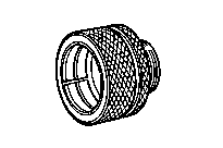
652 589 00 33 21
Hydraulic hose (complete)
Hand pump
Puller
Gripper
001 589 19 33 00
652 589 00 33 23
714 589 05 34 00


715 589 06 21 00
Gripper
Adjusting sleeve
Puller without spindle
Adapter
715 589 02 33 15
715 589 09 34 00
715 589 10 34 00


715 589 12 34 00
Hydraulic cylinder
Adapter
Adapter
Gripper
715 589 11 34 00
715 589 15 34 00
715 589 18 34 00

Gripper
715 589 19 34 00