
Drift
711 589 01 15 00


D26.50-0033-01
D26.50-0034-01
1 Clamp transmission main shaft in a vise with protective jaws so that the toothed end of the shaft points upwards.
2 Push on needle bearing (32).
3 Push on reverse gear wheel (33).

D26.50-0032-01
4 Push on thrust washer (34).
Installed position: Chamfered side (arrow) of thrust washer faces down.

D26.50-1151-01
5 If disassembled, insert sliding blocks (36) and compression springs (38) into synchronizer body (39) and push the shift sleeve (35) over the top. Pull up sliding blocks (36) on reverse side using a screwdriver until the balls (37) can be inserted from the front.
Installed position: The projecting shift splines on the shift sleeve (arrow A) and the high collar on the synchronizer body (arrow B) point upwards.

D26.50-0035-01
6 Push the assembled unit (35-39) onto the shaft in the correct position.
Installed position: The projecting shift splines on the shift sleeve (arrow A) point upwards towards the 5th gear wheel.


D26.50-0074-01
D26.50-0030-01
7 Install locking ring (40).
Replace locking ring. Do not over-expand the locking ring when installing.
8 Push on synchronizer ring (46) and synchronizer cone (41).


D26.50-0036-01
D26.50-0028-01
9 Push on needle bearing (42) and 5th gear wheel (43).
Installed position: The shift splines on the 5th gear wheel point downwards.
10 Push on thrust washer (44).
Installed position: The flat side of the thrust washer faces down.


D26.50-0026-01
D26.50-0027-01
11 Install locking ring (45).
12 Turn transmission main shaft over and clamp in vise.
13 Push on needle bearing (30).


D26.50-0024-01
D26.50-0025-01
14 Push on 1st gear wheel (29).
Installed position: The shift splines on the 1st gear wheel point upwards.
15 Push on synchronizer cone (28), synchronizer
ring (27) and synchronizer cone (26).
Oil the synchronizer cone and synchronizer ring.

D26.50-1152-01
16 If disassembled, insert sliding blocks (24) and compression springs (23) into 1st/2nd gear synchronizer body (25) and push the shift sleeve (21) over the top in the correct position. Pull up sliding blocks (24) on reverse side using a screwdriver until the balls (22) can be inserted from the front.
Installed position: The projecting shift splines on the shift sleeve (arrow A) and the high collar on the synchronizer body (arrow B) point upwards.


D26.50-0021-01
D26.50-0038-01
17 Push on synchronizer body with shift sleeve (21) in the correct position.
Installed position: The projecting shift splines (arrow) on the shift sleeve (21) must point upwards. Ensure that the sliding blocks are properly aligned with the 3 lugs on the upper synchronizer cone.
18 Install locking ring (17).
Replace locking ring. Do not over-expand the locking ring when installing.

D26.50-0019-01
D26.50-0020-01
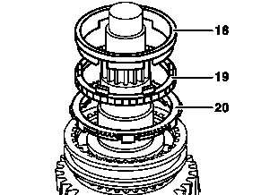
19 Push on synchronizer cone (18), synchronizer
ring (19) and synchronizer cone (20)
for 2nd gear.
Oil the synchronizer cone and synchronizer ring.
20 Push on needle bearing (16) and 2nd gear wheel (15).


D26.50-0017-01
D26.50-0018-01
21 Push on 2nd gear thrust washer (14) and drive home using the drift
(711 589 01 15 00).
22 Install locking ring (13).
Replace locking ring. Do not over-expand the locking ring.


D26.50-0015-01
D26.50-0080-01
23 Push on needle bearing (12) and 3rd gear wheel (11).
Installed position: Synchronizer cone points upwards.
24 Push on synchronizer ring (10).
Oil the synchronizer ring.

D26.50-1153-01
25 If disassembled, insert sliding blocks (6) and compression springs (8) into synchronizer body (9) and push the shift sleeve (5) over the top. Pull up sliding blocks (6) on reverse side using a screwdriver until the balls (7) can be inserted from the front.
Installed position: The projecting shift splines on the shift sleeve (arrow A) and the flat side of the synchronizer body (arrow B) point upwards.


D26.50-0012-01
D26.50-0013-01
26 Push on synchronizer body with shift sleeve (5) in the correct position.
Installed position: The projecting shift splines on the shift sleeve point upwards.
27 Install locking ring (4).
Replace locking ring. Do not over-expand the locking ring.

D26.50-0011-01
28 Push on synchronizer ring (3) and 4th gear synchronizer cone (2).
Oil the synchronizer ring and synchronizer cone.
29 Remove transmission main shaft from vise.