


N13.30-2025-01
N13.30-2026-01
N13.30-2027-01
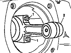


N13.30-2022-01
N13.30-2023-01
N13.30-2024-01
| Removing | ||
1 | Remove piston and cylinder liner of compressor | ||
2 | Unscrew hexagon nuts (1), take off conrod (2) and conrod bearing cap | Parts may drop into crankcase. | |
3 | Mark position of conrod bearing cap (3) in relation to conrod (2) | ||
4 | Take off conrod bearing shells | ||
5 | Insert conrod bearing shell (4) without oil groove into the conrod (2) | ||
6 | Insert conrod bearing shell (5) with oil groove into conrod bearing cap (3) | ||
7 | Connect conrod bearing cap to conrod | Pay attention to marking. | |
8 | Tighten hexagon nuts (1) fully | | |
| Measuring | ||
9 | Calibrate dial gage | | |
Set dial gage of 18 – 35 mm diameter to "0" with the 20 – 25 mm micrometer. | |||
10 | Measure conrod bearing bore | Measure conrod bearing bore at 3 points, vertically and on both sides offset about 30° from the separation points. | |
11 | Calibrate dial gage | | |
Set dial gage of 10 – 18 mm diameter to "0" with the 0 – 25 mm micrometer. | |||
12 | Measure inner diameter of conrod bearing bush | ||
13 | Take off conrod bearing cap again | ||
| Installing | ||
14 | Fit conrod (2) together with conrod bearing cap onto the camshaft journal | Lubricate conrod bearing shells and conrod bush with engine oil. | |
15 | Tighten hexagon nuts (1) fully | | |
16 | Install piston and cylinder liner of compressor | ||
17 | Install cylinder head compressor |
Compressor (compressed air system)

Dial gage
001 589 53 21 00