Modification notes
22.2.07 | Crankcase main bearing inside dia. in installed condition, standard | Engine 541.9 EURO standardⅡ as of engine no. 098132 engine 541.9 EURO standard Ⅲ Engine 542.9 EURO standard II as of engine no. 098132 engine 542.9 EURO standard Ⅲ |
Check values for a crankshaft
Number | Designation | Engine 541.9 | Engine 542.9 | ||
BE03.20-N-1001-02C | Main bearing journal dia. main bearing journal width (except main bearing fitted bearing journal) | Dia. standard | mm | 107.980 - 108.000 | 107.980 - 108.000 |
Dia. deviation 0.10 | mm | 107.880 - 107.900 | 107.880 - 107.900 | ||
Dia. deviation 0.25, | mm | 107.730 - 107.750 | 107.730 - 107.750 | ||
Dia. deviation 0.50 | mm | 107.480 - 107.500 | 107.480 - 107.500 | ||
Dia. deviation 0.75 | mm | 107.230 - 107.250 | 107.230 - 107.250 | ||
Dia. deviation 1.00 | mm | 106.98 - 107.000 | 106.98 - 107.000 | ||
BE03.20-N-1012-02C | Crankshaft main bearing inner dia. when installed | Default | mm | 108.056 to 108.102 | 108.056 to 108.102 |
Deviation 0.10 | mm | 107.956 to 108.002 | 107.956 to 108.002 | ||
Deviation 0.25 | mm | 107.806 to 107.852 | 107.806 to 107.852 | ||
Deviation 0.50 | mm | 107.556 to 107.602 | 107.556 to 107.602 | ||
Deviation 0.75 | mm | 107.306 to 107.352 | 107.306 to 107.352 | ||
Deviation 1.00 | mm | 107.056 to 107.102 | 107.056 to 107.102 | ||
Check values for a crankshaft
Number | Designation | Engine 541.9 | Engine 542.9 | ||
BE03.20-N-1001-02C | Main bearing journal dia. main bearing journal width (except main bearing fitted bearing journal) | Dia. standard | mm | 107.980 - 108.000 | 107.980 - 108.000 |
Dia. deviation 0.10 | mm | 107.880 - 107.900 | 107.880 - 107.900 | ||
Dia. deviation 0.25 | mm | 107.730 - 107.750 | 107.730 - 107.750 | ||
Dia. deviation 0.50 | mm | 107.480 - 107.500 | 107.480 - 107.500 | ||
Dia. deviation 0.75 | mm | 107.230 - 107.250 | 107.230 - 107.250 | ||
Dia. deviation 1.00 | mm | 106.980 - 107.000 | 106.980 - 107.000 | ||
BE03.20-N-1012-02C | Crankshaft main bearing inner dia. when installed | Default | mm | 108.069 to 108.118 | 108.069 to 108.118 |
Deviation 0.10 | mm | 107.969 to 108.018 | 107.969 to 108.018 | ||
Deviation 0.25 | mm | 107.819 to 107.869 | 107.819 to 107.869 | ||
Deviation 0.50 | mm | 107.569 to 107.618 | 107.569 to 107.618 | ||
Deviation 0.75 | mm | 107.319 to 107.369 | 107.319 to 107.369 | ||
Deviation 1.00 | mm | 107.069 to 107.118 | 107.069 to 107.118 | ||
Crankcase, timing case cover, end cover
Number | Designation | Engine | |||
BA01.40-N-1013-01D | Central bolt, main bearing cap to crankcase | Stage 1 | Nm | 320 | |
Stage 2 | ° | 90 | |||
BA01.40-N-1016-01D | Side bolt, main bearing cap to crankcase | Stage 1 | Nm | 120 | |
Stage 2 | ° | 90 | |||

001 589 53 21 00
Dial indicator
W03.20-0022-01
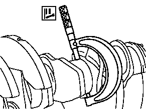
1 Clean bearing points on crankshaft with a chamois leather.
2 Measure main bearing journal dia. with the micrometer at two points (offset about 90°).
If one of measurements obtained is not within the tolerance, machine crankshaft.

W03.20-0023-01
3 Clean bearing points in crankcase and main bearing cap with a chamois leather.
4 Insert crankshaft bearing shells (2) into the crankcase in the order marked.
The locking lug (arrow) of crankshaft bearing shells (2) must be located in slots of the crankcase basic bores. Oil drillings in crankshaft bearing shell (2) and in crankcase must be aligned.

W03.20-0024-01
5 Insert crankshaft bearing shells (1) in marked order into main bearing caps (3, 4).
The locking lugs (arrows) of crankshaft bearing shells (1) must be located in the slots of the main bearing caps (3).

W03.20-0025-01
6 Fit main bearing caps (3, 4) onto the crankcase.
All main bearing caps (3, 4) have dowel pins and are marked with numbers. They must be installed in ascending order of the numbers, beginning from the front. Oil main bearing bolts (6, 7) and tighten in the specified order. First tighten the central main bearing bolts (6, 7), then the side bolts.

W03.20-0019-01
7 Use micrometer to set dial gauge and quick calipers to nominal dimension of the main bearing journal (preload 5 mm).
8 Use dial indicator and quick calipers to measure crankshaft bearing bores in crankcase at three points (A, B, C) (vertically and each about 30° away from separation points).
If one of measurements obtained (A, B, C) is not within tolerance, replace main bearing shells to match the measured main bearing journals. Main bearing shells are factory-supplied ready for installation and also in Deviations for repair work. No reworking is permissible.
9 Take off main bearing caps (3, 4) again.