D01.20-1021-09
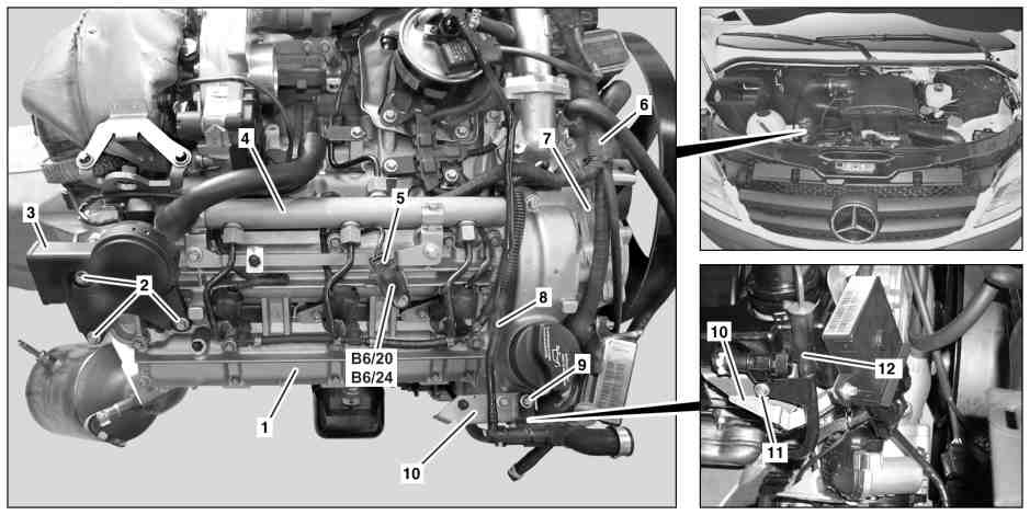
Shown on engine 642.992 |
1 | Cylinder head cover | 6 | Engine wiring harness | 11 | Screw | ||
2 | Screw/bolts (engine 642.992/993) | 7 | Vacuum pump | 12 | Guide tube | ||
3 | Oil separator (engine 642.992/993) | 8 | Drain pipe (code KL5 (Fuel filter with water separator)) | B6/20 | Rpm sensor (engine 642.992/993) | ||
4 | Rail | 9 | Screw/bolt (code KL5 (Fuel filter with water separator)) | B6/24 | Rpm sensor (engine 642.896/898) | ||
5 | Electrical connector | 10 | Bracket |

Shown on engine 642.992 |
1 | Cylinder head cover |
13 | Screw |
14 | Bolts |
15 | Connection fitting (engine 642.992/993) |
16 | Sealing ring |
17 | Radial shaft sealing ring |
18 | Cylinder head |
19 | Cover |
D01.20-1048-06

D01.20-1047-08
Shown on engine 642.896 |
20 | Oil separator (engine 642.896/898) | 22 | Bolts | |
21 | Vent hose |
| Remove/install | ||
1 | Remove rail (4) on right cylinder head (18) | ||
2.1 | Remove oil separator (3) | Engine 642.992/993 in model 906 | |
2.2 | Remove oil separator (20) and vent hose (21) from cylinder head | Engine 642.896/898 in model 906 | |
3 | Remove screw/bolts (14) and remove connection fitting (15) from cylinder head (18) | Engine 642.992/993 in model 906 | |
Bolt, connection fitting for oil separator to cylinder head | |||
4 | Clean sealing surfaces on connection fitting (15) and replace sealing ring (16). | Engine 642.992/993 in model 906 | |
5 | Check radial shaft sealing ring (17) of connection fitting (15) for damage | Engine 642.992/993 in model 906 | |
For damage | |||
| |||
Replace connection fitting (15) | |||
6 | Remove injectors for right cylinder head (18) | ||
7 | Disconnect electrical connection (5) from rpm sensor (B6 20 or B6/24) | ||
8 | Remove rpm sensor (B6/20 or B6/24) from the cylinder head cover (1) | When replacing the cylinder head cover (1). | |
Camshaft position sensor on cylinder head cover | |||
9 | Remove vacuum pump (7) | ||
10 | Remove drain hose at drain pipe (8) | Engine 642.896/898/992/993 in model 906 | |
11 | Remove screw/bolt (9), remove drain pipe (8) from holder (10) and swivel to the side | Engine 642.896/898/992/993 in model 906 | |
12 | Remove screw/bolt (11) and turn guide tube (12) oil dipstick to the side | Bolt, oil dipstick guide tube | |
13 | Remove engine wiring harness (6) to cylinder head cover (1) and expose | ||
14 | Remove exhaust gas recirculation | Engine 642.896/898/993 in model 906 | |
15 | Loosen and remove screw/bolts (13) in stages and in reverse order of the tightening procedure, for a cooled engine | ||
Installation: | |||
Screw/bolt, cylinder head cover to cylinder head | |||
16 | Press off cylinder head cover (1) to the corners (arrows) carefully from the cylinder head (18) using a suitable tool | ||
Notes on sealant path for cylinder head cover | |||
| |||
The cylinder head cover (1) can only be replaced in combination with the cylinder head (18). | |||
Installation: Replace the cover (19). | |||
Sealant, Loctite 5970, 50 ml | |||
Application gun | |||
If cylinder head cover (1) is damaged | |||
| |||
Replace cylinder head cover (1) and cylinder head (18) | |||
17 | Install in the reverse order | ||
Warning | Risk of accident from vehicle starting off by itself when engine running. Risk of injury (bruises and burns) resulting from working on the engine while it is being started or when it is running. | Secure vehicle to prevent it from starting off by itself. Wear closed and snug-fitting work clothes. Do not touch hot or rotating parts. | |
18 | Conduct engine test run and check engine for leaktightness in the area of the cylinder head cover (1) |

112 589 00 25 00
Application gun