
20 | Cover |
21 | Partition wall |
22 | Electrical wiring harness |
23 | Screw |
P09.40-A062-05
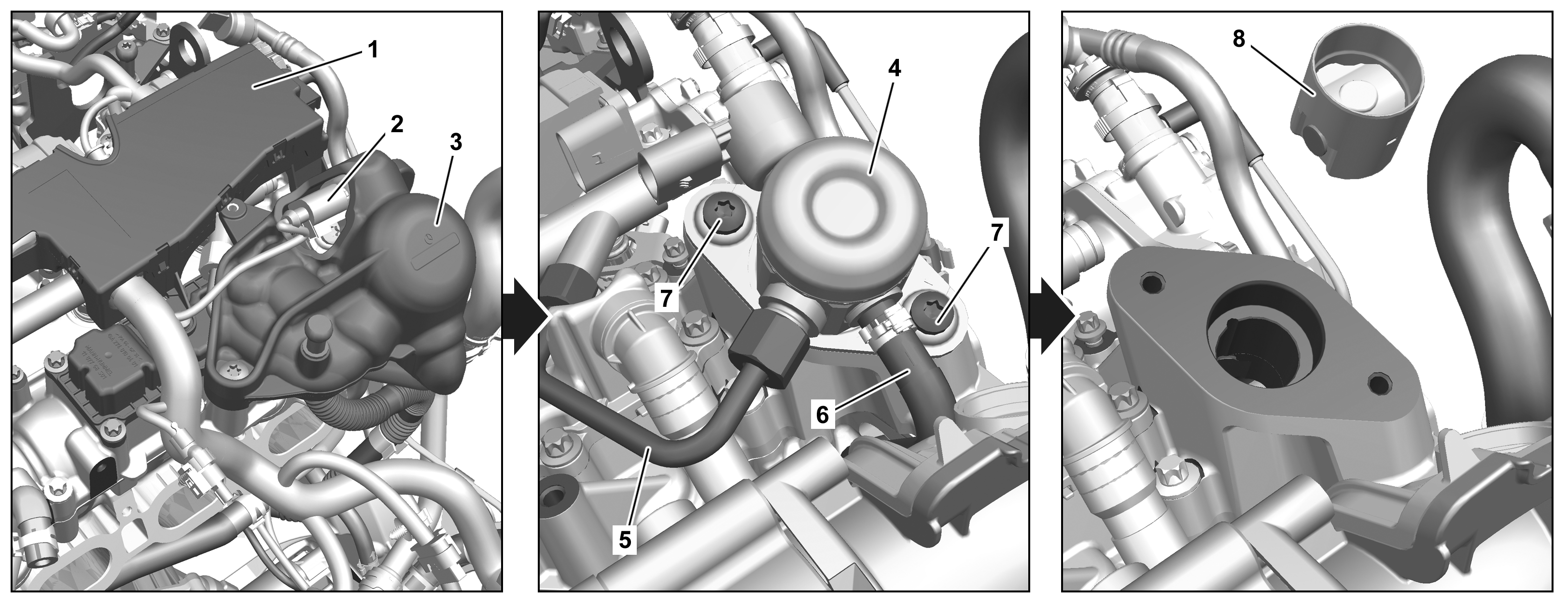
P07.02-A024-08
1 | Cable duct | 5 | High pressure pipe | |
2 | Electrical connector | 6 | Low pressure pipe | |
3 | Shielding | 7 | Screw | |
4 | Fuel high-pressure pump | 8 | Tappet element |
Danger | Risk of explosion caused by fuel igniting. Risk of injury to skin and eyes caused by fuel spraying out at high pressure | Keep all ignition sources out of hazard area. | |
Danger | Risk of explosion caused by fuel igniting, risk of poisoning caused by inhaling and swallowing fuel as well as risk of injury to eyes and skin caused by contactwith fuel. | No fires, sparks, open flames or smoking. Pour fuels into suitable and appropriately marked containers only. | |
Topical note | Notes on threaded connections fastened using a tightening angle-based tightening process | ||
Topical note | Information on preventing damage to electronic components due to electrostatic discharge | ||
Topical note | Notes on avoiding damage through contamination and foreign objects | ||
Note on calculation of tightening torque when using insertion or socket tools with various effective lengths | |||
General information on work on gasoline direct injection system | |||
| Remove | ||
1 | Remove cover for air/water duct. | ||
2 | Unclip cover (20) (arrows) and remove. | ||
3 | Unclip line of the inerting system from the partition (21). | Engine 274.9 in model 167 | |
4 | Unclip electrical wiring harness (22) from the partition (21). | ||
5 | Remove screws (23) and remove the partition (21) upward. | ||
6 | Remove engine compartment lining at rear. | ||
7 | Remove fuel pressure via the service connection. | ||
Dust cap at service connection | |||
Pressure hose | |||
8 | Disconnect ground line from battery. | ||
9 | Remove upper engine cover. | ||
| |||
10 | Remove engine air intake duct upstream of air filter. | ||
11 | Rotate engine using center bolt of crankshaft in direction of engine rotation to a crank angle (CKA) of 790 after top dead center (TDC) at cylinder 1. | Socket wrench bit | |
12 | Remove cable duct (1). | ||
13 | Release and disconnect the electrical connector (2). | ||
14 | Remove shielding (3). | Tightening procedure | |
Loosen the shielding (3) in the opposite direction to the tightening procedure. | |||
15 | Remove soundproofing from the high-pressure fuel pump (4). | ||
16 | Clean area around the high-pressure fuel pump (4) and high-pressure line (5). | Assembly cleaner | |
17 | Release fuel pressure in the fuel high-pressure circuit. | ||
18 | Remove high-pressure line (5) and seal connections with suitable stop plugs. | | |
Record plug | |||
Box wrench bit | |||
19 | Remove low-pressure line (6) from the high-pressure fuel pump (4) and seal connections with suitable stop plugs. | Record plug | |
Pliers for click clamps | |||
20 | Remove bolts_(7). | | |
21 | Remove fuel high-pressure pump (4). | ||
22 | Pull tappet element (8) out of the cylinder head cover. | ||
| Check | ||
23 | Check tappet element (8) for wear and damage. | If damage or wear is present, | |
| |||
replace tappet element (8). | |||
24 | Check high-pressure line (5). | ||
Assembly cleaner | |||
If damage is present, | |||
| |||
Install new high-pressure line(5). | |||
| Clean | ||
25 | Clean mount of the high-pressure fuel pump (4) in the cylinder head cover. | ||
| Install | ||
26 | Position the tappet element (8) in the cylinder head cover. | | |
27 | Install new sealing ring of the high-pressure fuel pump (4). | ||
28 | Position high-pressure fuel pump (4) in the cylinder head cover. | ||
29 | Screw in new screws (7). | | |
| |||
Bolt, high-pressure pump to cylinder head cover | |||
30 | Install high-pressure line (5). | ||
Union nut, fuel line to high-pressure pump | |||
Union nut, fuel line to fuel distributor | |||
Box wrench bit | |||
31 | Attach low-pressure line (6) with new clamp to the high-pressure fuel pump (4). | Pliers for click clamps | |
32 | Install soundproofing to the high-pressure fuel pump (4). | ||
33 | Install shielding (3). | Tightening procedure | |
Bolt for high-pressure pump shielding | |||
34 | Connect electrical connection (2). | ||
35 | Attach cable duct (1). | Screw, engine cable duct to cylinder head cover/charge-air distributor/oil separator/high-pressure pump shielding | |
36 | Install engine air intake duct upstream of air filter. | ||
37 | Connect ground line to the battery. | ||
38 | Switch on ignition. | | |
39 | Check high-pressure fuel circuit. | ||
| |||
Warning | Risk of accident from vehicle starting off by itself when engine running. Risk of injury (bruises and burns) resulting from working on the engine while it is being started or when it is running. | Secure vehicle to prevent it from starting off by itself. Wear closed and snug-fitting work clothes. Do not touch hot or rotating parts. | |
40 | Perform engine test run. While doing so, check engine for proper operation and leak tightness. | ||
41 | Install upper engine cover. | ||
| |||
42 | Install rear engine compartment lining. | ||
43 | Insert partition (21) and screw in screws (23). | Ensure that the partition (21) is seated correctly in the lower part of the partition. | |
Screw, upper engine compartment partition to lower engine compartment partition | |||
44 | Clip electrical wiring harness (22) onto the partition (21). | ||
45 | Clip line of the inerting system onto the partition (21). | Engine 274.9 in model 167 | |
46 | Clip in cover (20) (arrows). | ||
47 | Install cover for air/water duct. |


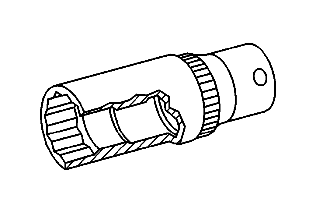
129 589 00 91 00
Record plug
171 589 00 37 00
Pliers for click clamps
000 589 80 03 00
Box wrench bit
001 589 65 09 00
Socket wrench bit

119 589 04 63 00
Pressure hose
Documente menționate
- ad0000p200006me
- ah0000p001501cw Indicaţie pentru calcularea cuplului de strângere la utilizarea de scule introduse cu diverse lungimi utile
- ah0000p002001a Indicaţii referitoare la îmbinările filetate, care au fost realizate conform procedeului de strângere în funcţie de unghiul de rotire
- ah0000p500001a Indicaţii pentru evitarea defecţiunilor din cauza impurităţilor şi corpurilor străine
- ah0700p200001a Indicaţii generale pentru lucrări la injecţia directă pe benzină
- ah0700p200001a
- ah5400p000101a Indicaţii pentru evitarea defectării componentelor electronice prin descărcare electrostatică
- ap0110p240501o Demontare, montare capace motor
- ar0702p081501mr Schemă de strângere ecranaj pompă de înaltă presiune
- ar0703p101002mr Montarea conductelor de înaltă presiune
- ar0703p101003mm Verificarea conductelor de înaltă presiune
- ar0703p101004mm Verificaţi circuitul de combustibil de presiune înaltă
- ar0703p146001mr Eliberaţi presiunea combustibilului prin intermediul supapei de service
- ar0703p146002mm Reducere presiunea combustibilului
- ar5410p0003me
- ar5410p0003me
- ar6120p1105me
- ar8310p1411me
- as0000z000501a Pericol de accident prin pornirea de pe loc cu motorul aflat în funcţionare. Pericol de rănire prin striviri şi arsuri la manipularea în timpul pornirii motorului sau cu motorul aflat în funcţionare
- as0716z000101a Pericol de explozie prin aprinderea carburantului. Pericol de rănire a pielii şiochilor datorită jetului de combustibil care se scurge
- as4700z000101a Pericol de explozie prin aprindere, pericol de intoxicare prin inhalare şi înghiţire de carburant cât şi pericol de rănire prin contactul pielii şi ochilor cu carburantul