SI25.20-B-0004A | Service Information: Notes on repairing the clutch booster | 12.02.16 |
Vehicle 368, 382, 384, 386, 634, 688, 693, 694, 695, 696, 958, 979
This service information has the objective of guiding on the procedures of checking and testing the tightness of the clutch cylinders, thus avoiding the unnecessary change and the consequent turned-down warranty claim.
Trucks and buses

B25.20-0040-01
B25.20-0041-01
Parts kit
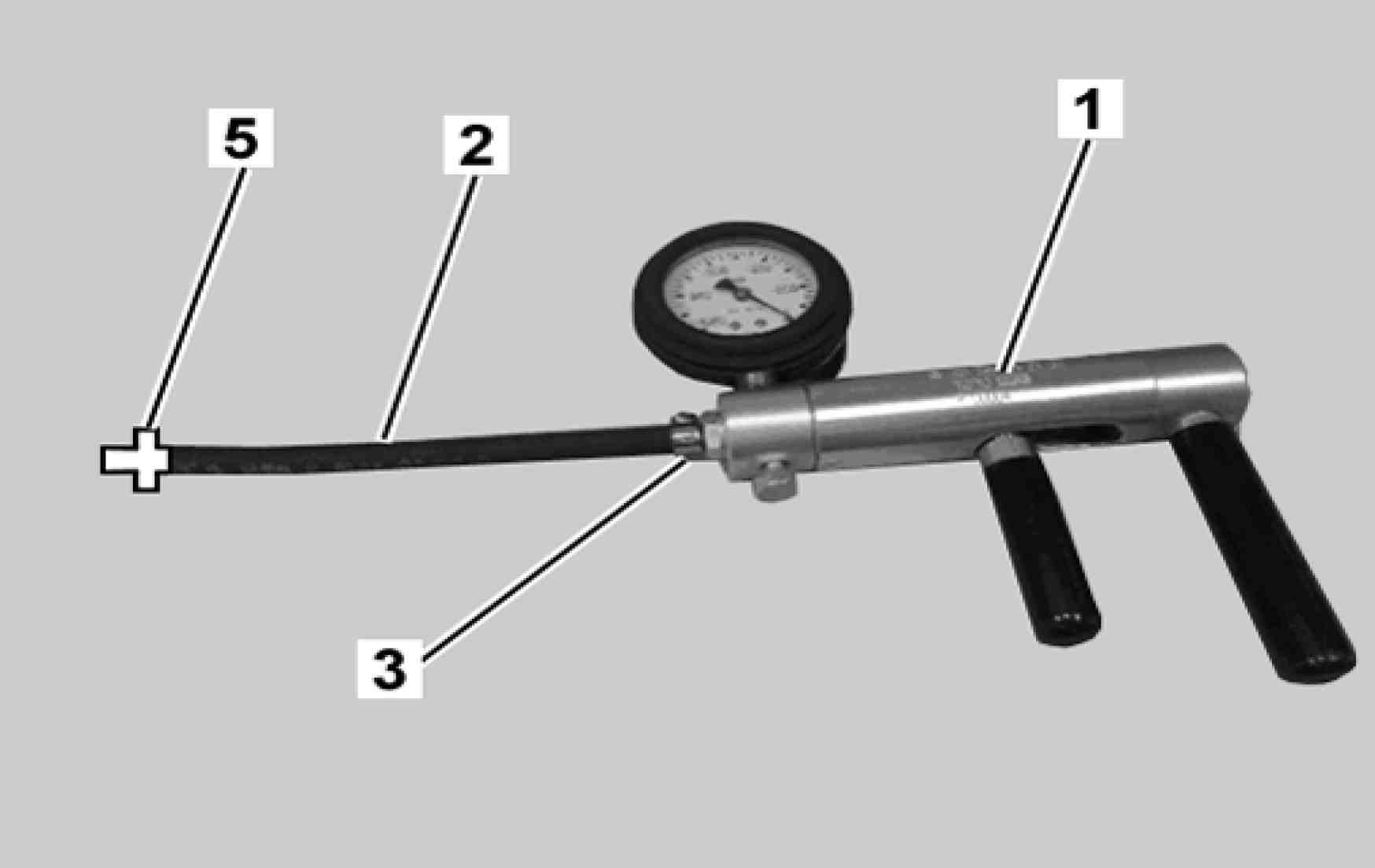
1 Vacuum gage W 001 589 73 21 00 (1 pc)
2 Hose A 688 997 82 82 (1 pc)
3 Clamp N 916002012100 (3 pcs)
4 Clutch hose A 384 295 10 35 (1 pc)
5 Connection A 000 295 01 36 (1 pc)
B25.20-0040-01
B25.20-0042-01
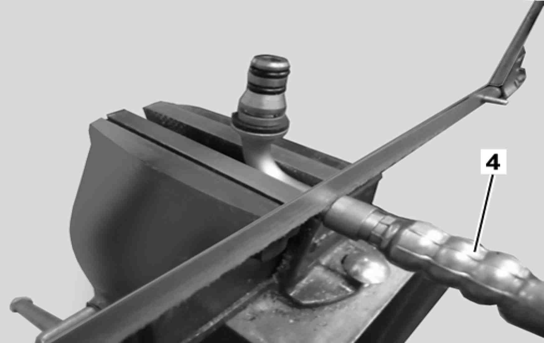
Vacuum gage adaptation for tightness test
1 Discharge the parts kit from the vacuum gage packing (1).
2 The hose (2) will have to be cut to 300 mm length.
3 The clutch hose (4) will have to be cut on the side of the steel tube protrusion, for re-using it.
After carrying out the cut it is important to deburr and to clean the cut area.

B25.20-0057-10
Alternatives for the steel tube of the hose (4)
An optional clutch hose of nr A 000 295 91 35 may be used, or to fabricate the steel tube following dimensions indicated on the sketch beside.
If fabricating the steel tube, it becomes necessary to apply the following sealing rings:
Sealing ring nr A 016 997 23 45 (1 pc) - Dimension 10.82 x 1.68 mm EPDM
O-rings nr A 026 997 08 48 (2 pcs) - Dimension 6.07x1.78 mm EPDM
B25.20-0041-01
Vacuum gage adaptation for the sealing packings test
Replace the steel tube (4) for the connection nr A 000 295 01 36 (1 pc).
B25.20-0043-01
B25.20-0044-01
Testing procedures of the metal master cylinders
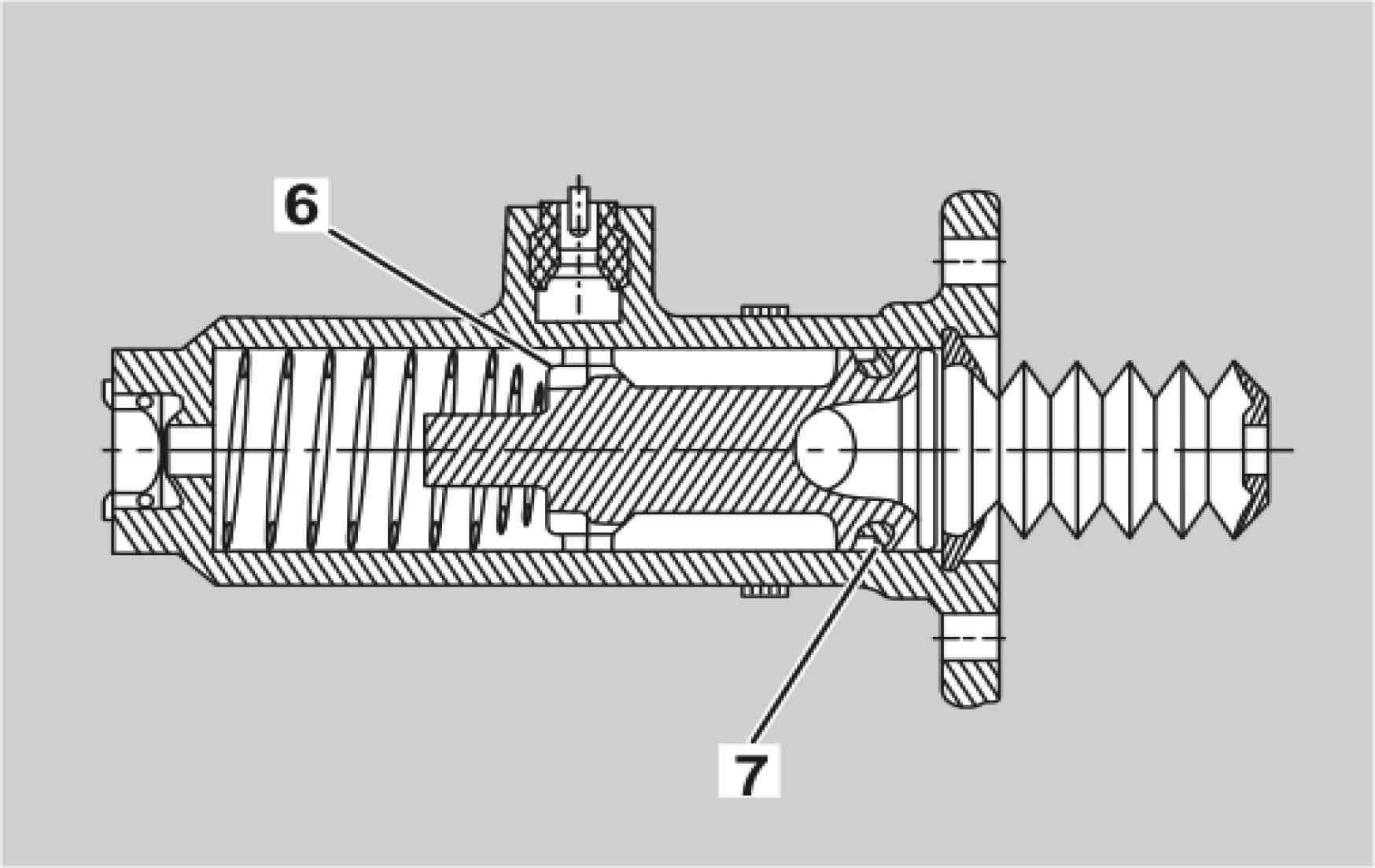
1 Test the pressure packing (6) and the sealing packing (7) of the master cylinders.
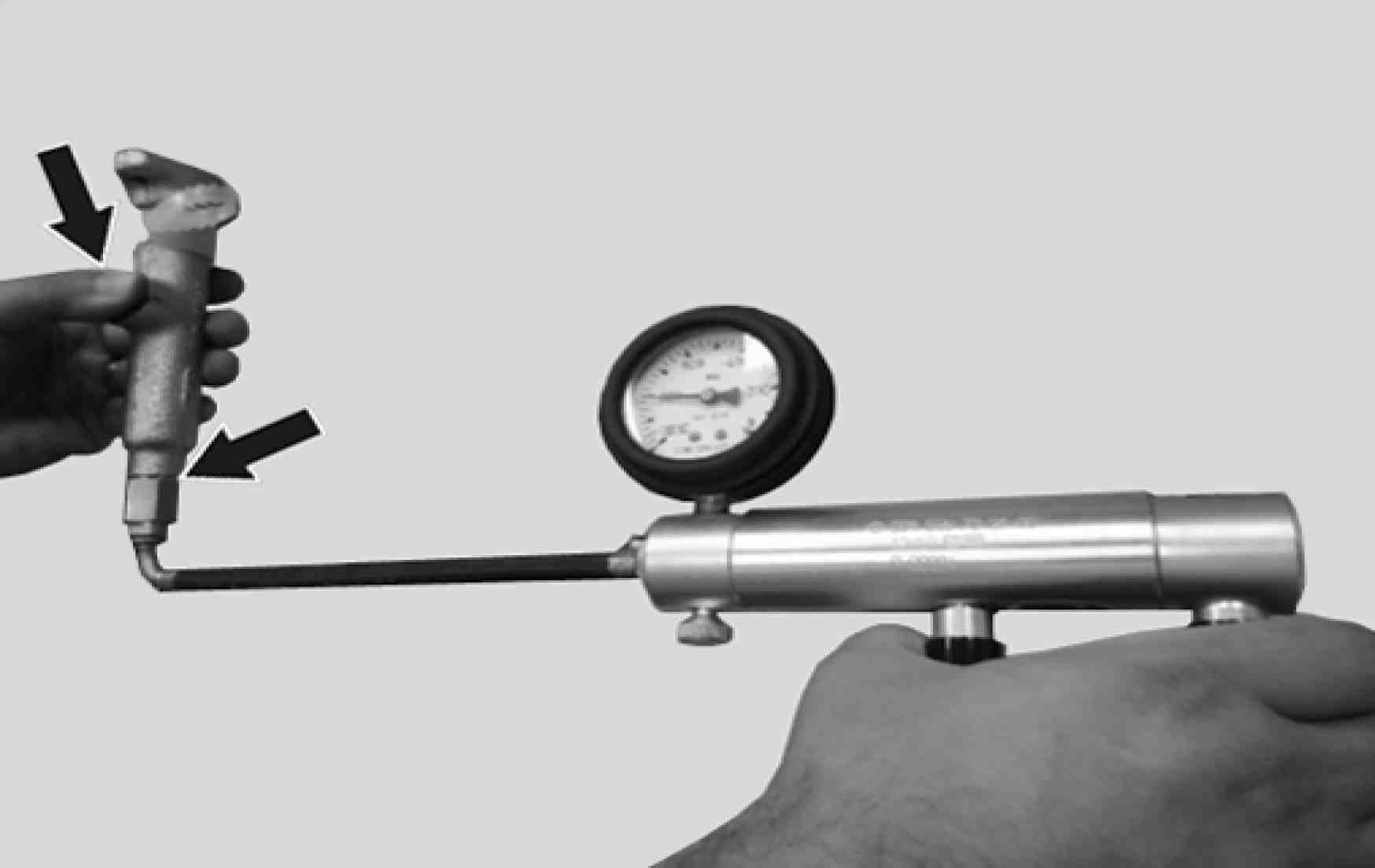
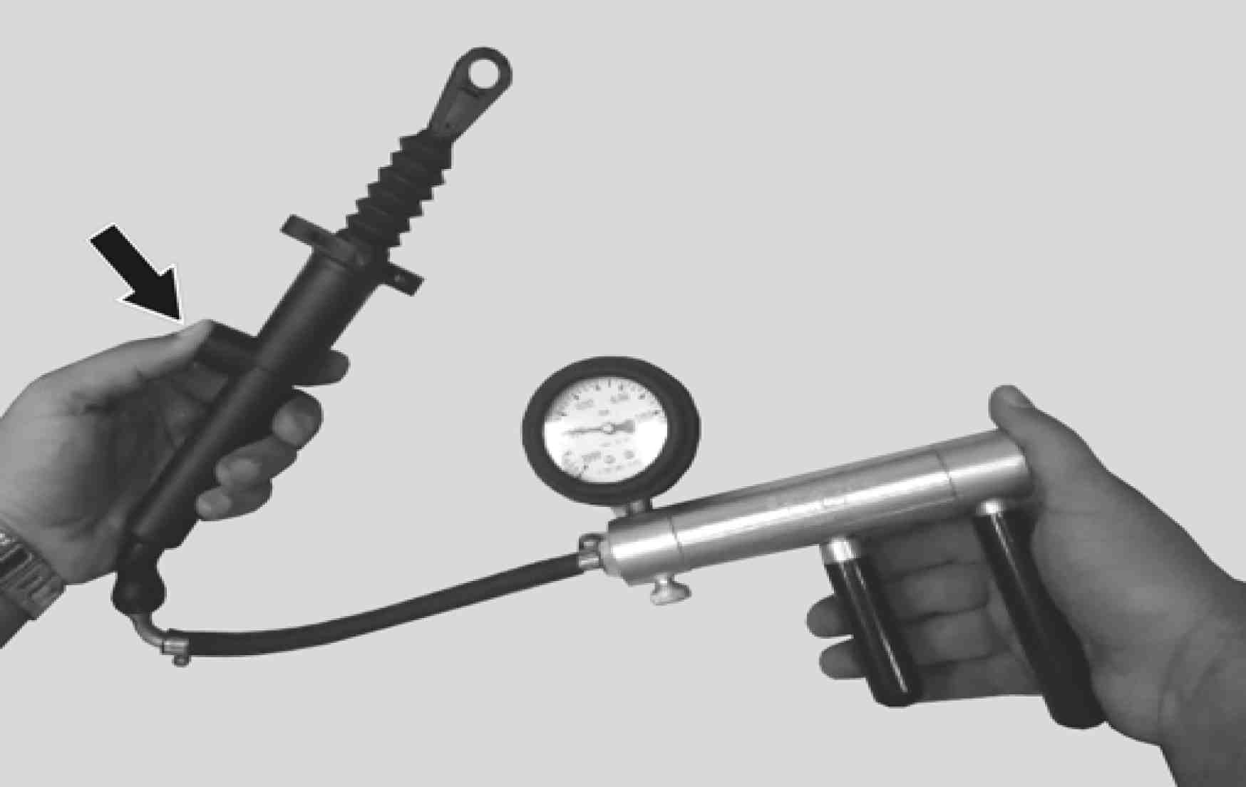
2 Assemble the vacuum gage and with the thumb, seal the vent area as per figure (arrow).
To install the vacuum gage on the master cylinders, a connection nr A 688 997 01 71 (M14 x 1) has to be used as per figure (arrow).
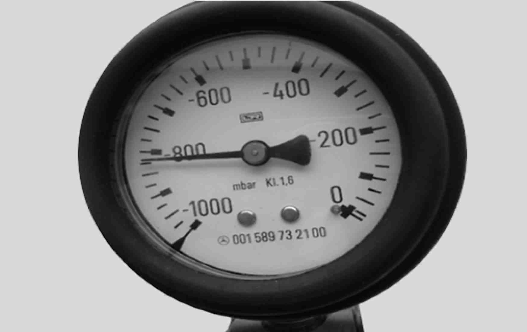
Pressure value must be between -700 and -850 mbar. The cylinders sealing will be considered normal if the reached value does not present a loss above -25 mbar for a period of, at least, 2 minutes.
B25.20-0045-01
B25.20-0048-01
Testing procedures of the plastic master cylinders
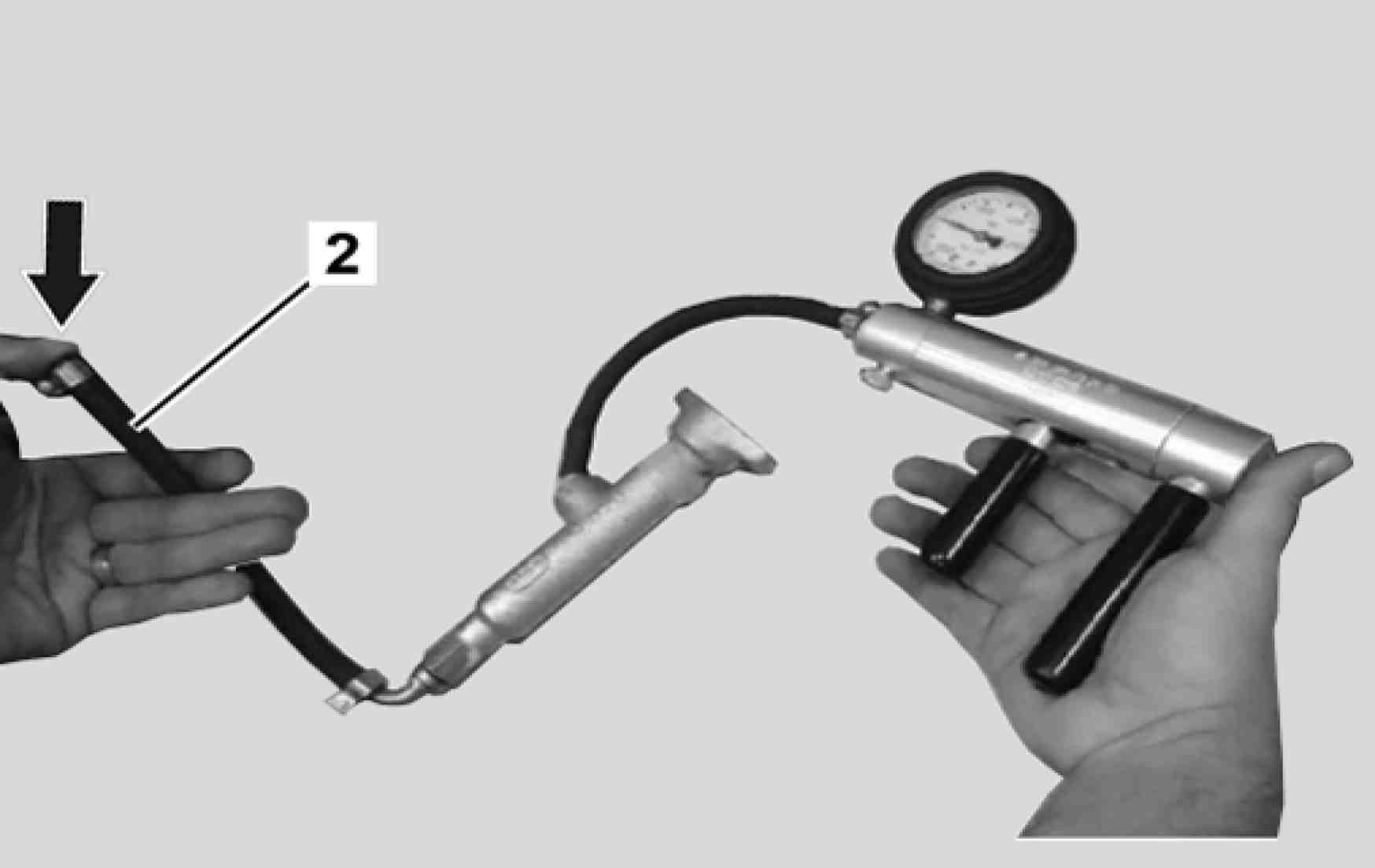
1 Assemble the vacuum gage and with the thumb, seal the vent area as indicated on the figure.
Pressure value must be between -700 and -850 mbar. The cylinders sealing will be considered normal if the reached value does not present a loss above -25 mbar for a period of, at least, 2 minutes.

B25.20-0046-01
B25.20-0047-01
Testing procedures of the sealing packing (7)
1 Assemble the vacuum gage on the inlet of the master cylinder and maintain the hose (2) of the previous testing situation (test of the pressure packing), seal the hose (2) with the finger, as indicated on the figure (arrow).
Pressure value must be between -700 and -850 mbar. The cylinders sealing will be considered normal if the reached value does not present a loss above -25 mbar for a period of, at least, 2 minutes.


B25.20-0049-01
B25.20-0050-01
Testing procedures of the slave cylinders
1 Close the bleeder to test the pressure packing (6), as indicated on the figure.

B25.20-0051-01
B25.20-0048-01
To install the vacuum gage on the slave cylinders, a connection nr A 688 997 01 71 (M14 x 1) has to be used as indicated on the figure (arrow).
Pressure value must be between -700 and -850 mbar. The cylinders sealing will be considered normal if the reached value does not present a loss above -25 mbar for a period of, at least, 2 minutes.

B25.20-0054-10
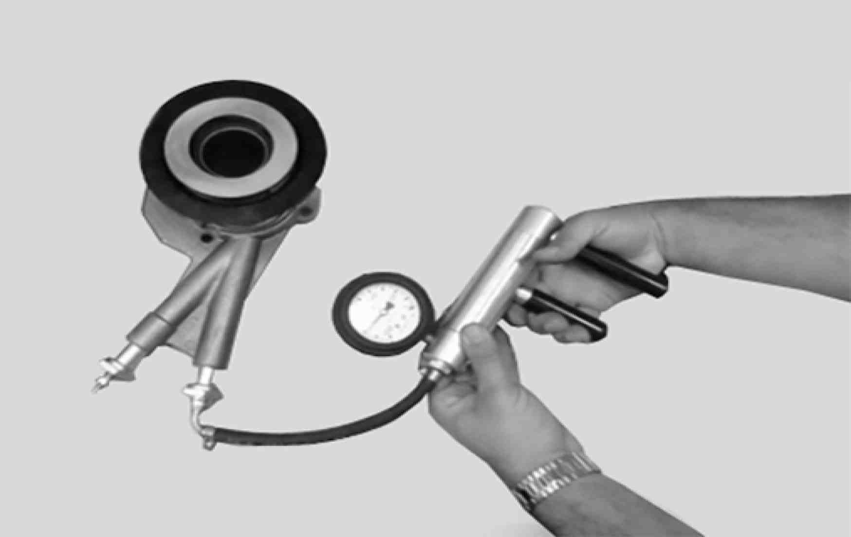
CSC cylinder testing procedure - pressure packing (6)
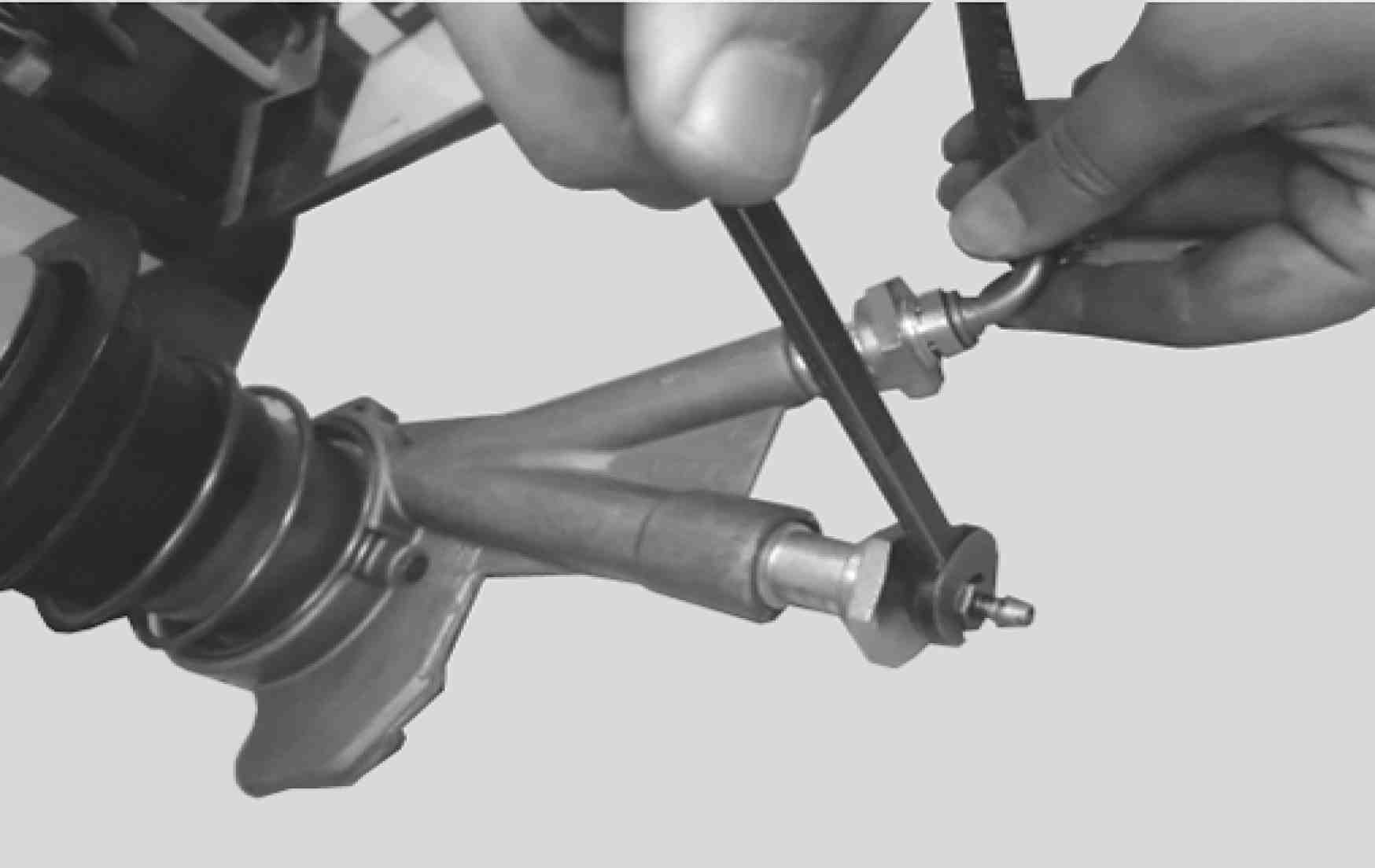
1 To test the pressure packing (6), close the bleeder as indicated on the figure.
B25.20-0055-01
B25.20-0056-01
2 Connect the vacuum gage as indicated on the figure.
Pressure value must be between -700 and -850 mbar. The cylinders sealing will be considered normal if the reached value does not present a loss above -25 mbar for a period of, at least, 2 minutes.