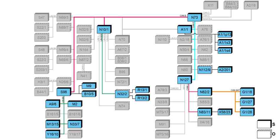
S83.00-A018-79
Auxiliary climate control at departure time, block diagram |
A1/1 | Instrument cluster (KI) control unit | N82/2 | Battery management system control unit | |
A1/1p13 | Multifunction display | N83/11 | Alternating current charger for high-voltage battery | |
A1/1s3 | Instrument, switch and controls illumination button, bright | N112/9 | HERMES control unit | |
A1/1s4 | Instrument, switch and controls illumination button, dark | N127 | Drive train control unit | |
A2/201 | HERMES GSM antenna | R13/1 | Driver seat cushion heater pad | |
A9/6 | Electric refrigerant compressor | R13/2 | Driver seat backrest heater pad | |
B10/5 | Evaporator temperature sensor | S98 | Air conditioning control and operating unit (front & rear KLA) | |
G1/18 | High-voltage battery 1 | X58/23 | 230 V feed socket | |
G1/27 | High-voltage battery 2 | Y16/10 | Condensation prevention switchover valve | |
G1/28 | High-voltage battery 3 | CAN B | Interior CAN | |
M2 | Blower motor | CAN BAT | Battery management system CAN | |
M9 | Blower with interior air temperature sensor | CAN E | Chassis CAN | |
M13/15 | Electric auxiliary water pump | CAN L | Hybrid CAN | |
N10/1 | Signal acquisition and actuation module (SAM) control unit | LIN B8 | AC control LIN | |
N32/2 | Seat heater/ventilation control unit (with code H16 (Seat heating for driver)) | LIN B28 | Heater LIN | |
N33/7 | High-voltage PTC heater control unit | O | Optional | |
N73 | Electronic ignition lock (EZS) control unit | S | Default |
Function requirements for auxiliary climate control at departure time, general
Circuit 15 off
Auxiliary climate control preset
Vehicle connected to charging station
Auxiliary climate control at departure time, general
Depending on requirements, the vehicle interior of the parked vehicle can be pre-heated or pre-cooled before starting a journey, as long as the charging cable is plugged in.
The auxiliary climate control can only be activated/deactivated and the departure time adjusted via a web-based system using a browser or an app with a smartphone, a tablet or a PC, not via the instrument cluster settings.
If a departure time has been set there, it can be permanently deactivated once in the "Charging" menu of the instrument cluster (IC) control unit (A1/1) using the instrument, switch and controls illumination buttons (A1/1s3, A1/1s4). It can only be set again using the web-based system. If no departure time is activated, the multifunction display (A1/1p13) of the instrument cluster (IC) control unit shows the message "Departure time inactive" in place of the menu.
Activation of the auxiliary climate control and departure time is indicated by symbols in the status area at the bottom of the multifunction display.
The "Charging" menu is only available when a charging cable is connected.
The function description for the auxiliary climate control at departure time is structured as follows:
Auxiliary climate control at departure time, function
Function sequence for pre-cooling
Function sequence for pre-warming
Auxiliary climate control at departure time, function
The departure time can only be set, selected and activated via a web-based system using a browser or an app, e.g. with a smartphone, a tablet or a PC.
With web-based programming, the HERMES control unit (N112/9) receives the requests over the HERMES GSM antenna (A2/201).
The HERMES control unit sends the received requests to the electronic ignition lock (EZS) (N73) control unit and the powertrain control unit (N127). The powertrain control unit then sends the activated departure time to the instrument cluster control unit (IC), which then saves it.
The air conditioning system control and operating unit (front & rear AAC) now calculates the necessary start time for the pre-entry climate control and sends this to the powertrain control unit. Once the starting time is reached, the powertrain control unit sends the request for pre-entry climate control to the air conditioning system control and operating unit (front & rear AAC).
The air conditioning system control and operating unit (front and rear AAC) also continuously sends information on the operating status of the pre-entry climate control to the HERMES control unit.
The information stored there can be retrieved using the smart phone, tablet or PC, for example. The information is provided by request only.
The HERMES control unit transmits the data via the HERMES GSM antenna.
When the vehicle is connected to power supply equipment, priority is given to charging the high-voltage batteries (G1/18, G1/27, G1/28) to the defined minimum charge level. Auxiliary climate control at departure time is only activated following this.
To operate the auxiliary climate control at departure time, the air conditioning system control and operating unit (front & rear AAC) evaluates the following information:
Interior temperature
Target temperature on air conditioning system control and operating unit (front & rear AAC)
Ambient temperature
Solar radiation
If the interior temperature is above the selected specified temperature, the vehicle is cooled. If the interior temperature is below the selected specified temperature, the vehicle is heated.
The vehicle interior is cooled or heated until the desired temperature in relation to the set departure time has been reached. To do this, the auxiliary climate control is activated max. 50 minutes in advance. If the departure is delayed, the vehicle interior is air-conditioned for an additional 5 minutes. Auxiliary climate control is ended when the vehicle is started or when 5 minutes have passed since the selected departure time elapsed.
Function sequence for pre-cooling
If cooling is required, the automatic air conditioning function is started:
The air conditioning system control and operating unit (front & rear AAC) actuates the electric refrigerant compressor (A9/6) and the blower motor (M2) via the air conditioning control LIN (LIN B8).
Detailed information on the individual measures is available in the "Electric vehicle climate control function" description.
Function sequence for pre-warming
If heating is required, the following functions are started:
Heat boosting via the high-voltage PTC heater control unit (N33/7)
The air conditioning system control and operating unit (front & rear AAC) actuates the high-voltage PTC heater control unit via the air conditioning control LIN.
The high-voltage PTC heater control unit heats the coolant. The coolant temperature in the heating circuit is registered by the condenser pressure and temperature sensor (B161/6) and read in by the air conditioning system control and operating unit (front & rear AAC). When the coolant has reached a temperature of 35 °C, the air conditioning system control and operating unit (front & rear AAC) actuates the electric additional water pump, the condensation prevention switchover valve (Y16/10) and the blower motor.
The electric additional water pump pumps the coolant from the high-voltage PTC heater to the heater core, thus allowing the vehicle interior to be heated.
Seat heating (with code H16 (Seat heating for driver))
The air conditioning system control and operating unit (front & rear AAC) sends the request to switch on the seat heating over the interior CAN (CAN B) to the signal acquisition and actuation module control unit (SAM) (N10/1). The signal acquisition and actuation module (SAM) control unit sends the seat heating transmit via the heater LIN (LIN B28) to the seat heating/ventilation control unit (N32/2), which actuates the driver seat cushion heater pad (R13/1) and the driver seat backrest heater pad (R13/2) directly.
The seat heating is actuated shortly before the departure time and remains activated after the vehicle has been started.