
P33.10-2164-09
Shown on model 171.442
1 Front axle carrier
1c Screw
3 Screw
4 Screw
5 Bolts
Y10 SPS solenoid valve (model 171 with code (213) Speed-sensitive power steering)
Direct steering solenoid valve (model 172 with code (213) Direct steering)
6 Brake hose
7 Screw
8 Bracket
77 Stabilizer bar
78 Stabilizer bar link rod
Modification notes
5.3.12 | "Unclip electrical feed lines" added | Step 5 | |
Detach cable tie from front axle carrier, added | Step 24 |
| Remove/install | ||
Danger! | Risk of death caused by vehicle slipping or toppling off of the lifting platform | Align vehicle between columns of vehicle lift and position four support plates at vehicle lift support points specified by vehicle manufacturer. | |
Danger! | Risk of poisoning caused by swallowing brake fluid. Risk of injury caused by brake fluid coming into contact with skin and eyes | Only pour brake fluid into suitable and appropriately marked containers. Wear protective clothing and eye protection when handling brake fluid. | |
| Notes on self-locking nuts and bolts | ||
1 | Move steering wheel all the way to the rear | ||
2 | Deactivate easy entry/exit function for driver seat and steering wheel | Model 171 with code (275) Memory package (driver seat, steering column, mirrors) | |
Model 172 with code (275) Memory package for electrically adjustable front seats | |||
Easy entry/exit function for driver seat and steering wheel must be deactivated. Otherwise the steering wheel moves to a different position if, e.g. the driver door is opened or closed. The cover on the crossmember above the windshield or the windshield itself may be damaged if the holding device is installed. | |||
3 | Rotate steering wheel into center position and fix in position with retainer | The steering wheel must not be turned when detaching steering coupling. Otherwise the clock spring contact will be destroyed. | |
Front wheels in straight-ahead position. | |||
Holding device | |||
4 | Open engine hood and move to vertical position | ||
5 | Remove air filter housing | Model 171.473 | |
Model 172.475 | |||
Danger! | Risk of injury to skin or eyes caused by hydraulic fluid spraying out under high pressure. Risk of poisoning caused by swallowing hydraulic fluid | Depressurize hydraulic system completely before starting any work on system. Wear protective clothing and safety glasses. | |
6 | Suction off oil from expansion reservoir of power steering | Hand pump | |
7 | Remove both front wheels | ||
8 | Disconnect brake line from brake hose (6) on left and right | ||
9 | Remove both front suspension struts | Model 171 | |
Model 172 | |||
10 | From above, insert 3 bolts each into the suspension strut supports on the vehicle and secure with nuts | In order to be able to fix the engine lifting device in position. | |
11 | Mount engine hoist | Model 171 with engine 113, 271 Model 172 with engine 271 | |
Model 171 engine 272 Model 172 with engine 152, 276, 651 | |||
Engine hoist | |||
12.1 | Remove lower engine compartment paneling | Model 171 | |
Model 172 with gasoline engine | |||
12.2 | Remove lower bottom sections of soundproofing | Model 172 with diesel engine | |
13 | Remove diagonal strut of front axle carrier (1) | Installation: The bolts of the diagonal struts must not be tightened until the vehicle is standing with its wheels on the ground. | |
| |||
14.1 | Remove rear section of fender liner in left and right front fender | Model 171 | |
14.2 | Remove fender liner in left and right front fender | Model 172 | |
15 | Undo bolt (7) and detach steering coupling on steering shaft | Engine 271 | |
Engine 113, 152, 272, 276, 651 | |||
16 | Undo bolt (4) and detach oil lines from the rack-and-pinion steering | Seal off line connections with plugs. | |
Installation: Replace sealing rings. | |||
| |||
Set of stop plugs | |||
17 | Detach bracket (8) of hydraulic line from front axle carrier (1) | Except model 172.475 | |
Model 171 | |||
Model 172 | |||
18 | Detach return line of P/S from rack-and-pinion steering on cooler of P/S at connecting point | Model 172.475 | |
Replace CLIC clamp. | |||
Seal off return line with stop plugs. | |||
| |||
19 | Undo bolts (5) of retaining bracket on stabilizer bar (77) | | |
20 | Remove bolts (3) from engine mounts | Model 171 with engine 271, 272 | |
Model 171 with engine 113 | |||
Model 172 | |||
21 | Mount protective washers for brake cover plate | ||
Guard plate | |||
22 | Detach connectors from front axle electrical distributors and unclip electrical lines from brackets | ||
23 | Detach connector from SPS solenoid valve (Y10) or direct steering solenoid valve (Y10) | Model 171 with code (213) Speed-sensitive power steering, Model 172 with code (213) Direct steering | |
24 | Detach cable tie from front axle carrier and place electrical line of SPS solenoid valve (Y10) or direct steering solenoid valve (Y10) to one side | Place electrical line to one side. Otherwise the electrical line will be damaged when the front axle is lowered. | |
25 | Support front axle using transmission jack and transmission plate | Transmission jack gotis://H_00.10_01.0 Passenger car transmission platform gotis://A_25/35/49_02.0 | |
26 | Unscrew bolts (1c) of front-axle carrier (1) | The bolts (1c) are self tapping. Therefore, do not remove the bolts (1c) using an impact wrench/driver and never recut the thread in the longitudinal member. Otherwise the thread in the longitudinal member may be damaged. | |
Replace bolts (1c). | |||
| |||
| Notes on bolted connections with self tapping screws | ||
27 | Lower front axle | Secure front axle to prevent it falling. | |
28 | Install in the reverse order | ||
29 | Bleed brake system | Model 171 | |
Model 172 | |||
30 | Fill power steering pump and bleed | Model 171 with engine 113, 271, 272 Model 172 with engine 152, 271, 276, 651 | |
31 | Perform wheel alignment check | Model 171 | |
Model 172 |
Engine suspension, engine mounts, engine supports
Number | Designation | Engine | Engine | ||
BA22.10-P-1006-01O | Bolt, front engine mount to front axle carrier | Nm | 35 | 35 | |
Engine suspension, engine mounts, engine supports
Number | Designation | Engine | ||
BA22.10-P-1001-01S | Bolt, front engine mount to front axle carrier | Nm | 35 | |
Engine mount, engine support (engine side)
Number | Designation | Model | |||
BA22.10-P-1002-03E | Bolt, front engine mount to front axle carrier | Nm | 35 | ||
Front axle stabilizer bar
Number | Designation | Model | Model | ||
BA32.20-P-1007-02B | Bolt, retaining bracket to longitudinal member | Nm | 23 | 23 | |
Front axle carrier
Number | Designation | Model | Model | |
BA33.10-P-1005-01A | Bolt, front axle carrier to longitudinal member | Nm | 80 | 120 |
Steering gear
Number | Designation | Model | Model | ||
BA46.20-P-1001-01F | Bolt, oil line retaining plate to rack-and-pinion steering | Nm | 18 | 18 | |
Power steering pump
Number | Designation | Model | ||
BA46.30-P-1015-01R | Bolt, high-pressure hose to major assembly carrier | Nm | 10 | |
Power steering pump
Number | Designation | Model | Model 171 | Model 171 | ||
BA46.30-P-1014-01D | Bolt, power steering oil line to front axle carrier | Nm | 9 | 9 | 9 | |
Frame floor assembly
Number | Designation | Model 171 | Model | |
BA61.10-P-1006-01A | Self-locking bolt, front diagonal strut to frame floor or front axle carrier | Nm | 60 | 60 |


129 589 01 21 00
Engine lifting fixture
Holding device
Guard plate
Set of stop plugs
220 589 01 31 00
240 589 00 61 00
129 589 00 91 00
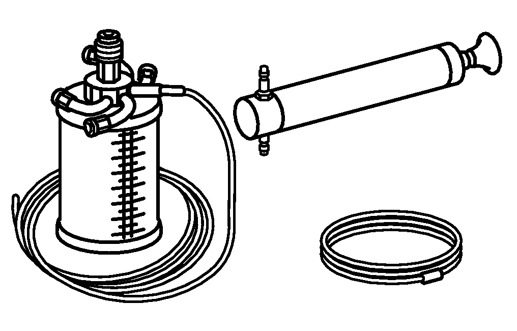
Hand pump
210 589 00 71 00
Powiązane dokumenty
- ah0000n000101a Wskazówki dotyczące samozabezpieczających śrub i nakrętek
- ah0000p000701sf Wskazówki dotyczące połączeń śrubowych z samonacinającymi śrubami
- ap4010p4050v Demontaż i montaż kół, w razie potrzeby przełożenie
- ar0910p1150ac Demontaż i montaż obudowy filtra powietrza
- ar0910p1150mmi
- ar3225p1017cw Demontaż i montaż przednich kolumn zawieszenia
- ar3225p1017v
- ar3310p010001v
- ar3310p010001va Zakładanie jarzma nośnego silnika, podnoszenie silnika
- ar3310p010003v
- ar3310p010006v
- ar4020p0200ew Wykonanie pomiarów podwozia
- ar4020p0200v
- ar4200p010001a Zamontowanie osłony zabezpieczającej na osłonach tarcz hamulcowych
- ar4210p0010cw Odpowietrzanie układu hamulcowego
- ar4210p0010v
- ar4210p0013v Wymiana elastycznych przewodów hamulcowych
- ar4610p0621v Wymiana osłony wału kierowniczego
- ar4610p0621va
- ar4630p0010v Napełnij i odpowietrz pompę wspomaganej przekładni kierowniczej.
- ar5430p100002edv
- ar5430p100002w
- ar6120p1105v
- ar6120p1105w
- ar8810p1300v
- ar8810p1300w
- ar8840p1000v
- ar9430p5300w
- as0000z001001a Zagrożenie życia na skutek ześlizgnięcia lub spadnięcia pojazdu z podnośnika.
- as0000z001301a Niebezpieczeństwo obrażeń oczu i skóry przez płyn hydrauliczny pod ciśnieniem. Niebezpieczeństwo zatrucia w wyniku spożycia płynu hydraulicznego
- as4250z000101a Niebezpieczeństwo zatrucia na skutek połknięcia płynu hamulcowego. Niebezpieczeństwo zranienia wskutek kontaktu skóry i oczu z płynem hamulcowym